Dtc P17A8 Transfer Shift Motor Control Circuit Circuit Open
Drivetrain. Land Cruiser. Urj200, 202 Grj200 Vdj200
DESCRIPTION
WIRING DIAGRAM
INSPECTION PROCEDURE
CHECK HARNESS AND CONNECTOR (4 WHEEL DRIVE CONTROL ECU - TRANSFER SHIFT ACTUATOR ASSEMBLY)
INSPECT TRANSFER SHIFT ACTUATOR ASSEMBLY (HIGH-LOW TRANSFER SHIFT
MOTOR)
DTC P17A8 Transfer Shift Motor Control Circuit Circuit Open |
DESCRIPTION
This DTC is output when an open circuit is detected in the high-low transfer shift motor drive circuit.DTC No.
| DTC Detection Condition
- Diagnosis Condition
- Malfunction Status
- Malfunction Time
- Other
| Trouble Area
|
P17A8
| - When switching between high and low or during switching operation (high-low transfer shift motor operating) with ignition switch turned to ON
- Open circuit in the high-low transfer shift motor drive circuit
- 0.03 seconds or more
- 1 trip detection logic
| - Wire harness and connector
- 4 wheel drive control ECU
- Transfer shift actuator assembly
|
WIRING DIAGRAM
Refer to DTC P17A9 (Click here).
INSPECTION PROCEDURE
| 1.CHECK HARNESS AND CONNECTOR (4 WHEEL DRIVE CONTROL ECU - TRANSFER SHIFT ACTUATOR ASSEMBLY) |
Disconnect the A28 4 wheel drive control ECU connector.
Disconnect the C38 transfer shift actuator assembly connector.
Measure the resistance according to the value(s) in the table below.
- Standard Resistance:
Tester Connection
| Condition
| Specified Condition
|
A28-2 (HM1) - C38-1 (HM1)
| Always
| Below 1 Ω
|
A28-6 (HM2) - C38-2 (HM2)
| Always
| Below 1 Ω
|
| | REPAIR OR REPLACE HARNESS OR CONNECTOR |
|
|
| 2.INSPECT TRANSFER SHIFT ACTUATOR ASSEMBLY (HIGH-LOW TRANSFER SHIFT
MOTOR) |
Disconnect the C38 transfer shift actuator assembly connector.
Measure the resistance according to the value(s) in the table below.
- Standard Resistance:
Tester Connection
| Condition
| Specified Condition
|
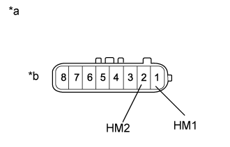
1 (HM1) - 2 (HM2)
| Always
| 1.5 to 100 Ω
|
Text in Illustration*a
| Component without harness connected
(Transfer Shift Actuator Assembly)
|
*b
| High-low Transfer Actuator Side
|
- Result:
Result
| Proceed to
|
OK
| for LHD
| A
|
for RHD
| B
|
NG
| C
|
| |
|
| | REPLACE TRANSFER SHIFT ACTUATOR ASSEMBLY (Click here) |
|
|