Drivetrain. Land Cruiser. Urj200, 202 Grj200 Vdj200
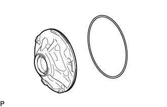
REMOVE OIL PUMP O-RING
REMOVE TRANSMISSION REVOLUTION SENSOR (NT)
REMOVE NO. 1 CHECK VALVE SUB-ASSEMBLY
FIX OIL PUMP ASSEMBLY
REMOVE CLUTCH DRUM OIL SEAL RING
REMOVE NO. 1 BRAKE PISTON
REMOVE CLUTCH DRUM THRUST WASHER
INSPECT NO. 1 BRAKE PISTON RETURN SPRING SUB-ASSEMBLY
REMOVE STATOR SHAFT ASSEMBLY
REMOVE FRONT OIL PUMP BODY O-RING
INSPECT STATOR SHAFT ASSEMBLY
INSPECT CLEARANCE OF OIL PUMP ASSEMBLY
REMOVE FRONT OIL PUMP DRIVE GEAR
REMOVE FRONT OIL PUMP DRIVEN GEAR
REMOVE FRONT OIL PUMP OIL SEAL
| 1. REMOVE OIL PUMP O-RING |
Remove the oil pump O-ring from the oil pump assembly.
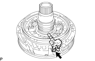
| 2. REMOVE TRANSMISSION REVOLUTION SENSOR (NT) |
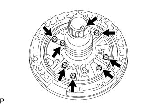
Using a T30 ''TORX'' socket wrench, remove the bolt and transmission revolution sensor (NT) and clamp from the oil pump assembly.
Detach the clamp to remove the transmission revolution sensor (NT) from the clamp.
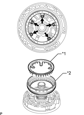
| 3. REMOVE NO. 1 CHECK VALVE SUB-ASSEMBLY |
Remove the bolt and check ball cover.
Remove the compression spring and No. 1 check valve sub-assembly from the oil pump assembly.
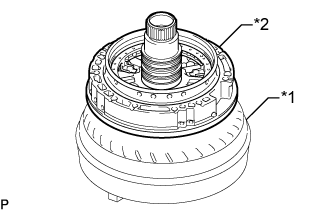
Place the oil pump assembly on the torque converter assembly.
Text in Illustration*1
| Torque Converter Assembly
|
*2
| Oil Pump Assembly
|
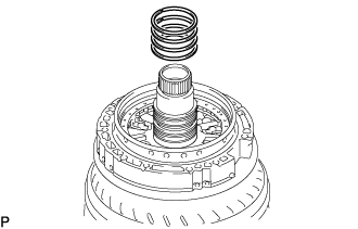
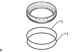
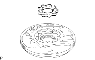
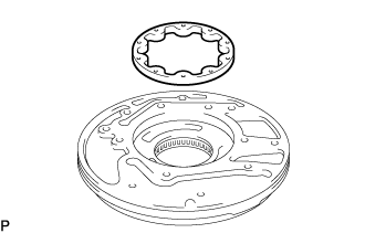
| 5. REMOVE CLUTCH DRUM OIL SEAL RING |
Remove the 4 clutch drum oil seal rings from the stator shaft assembly.
| 6. REMOVE NO. 1 BRAKE PISTON |
Using a T30 ''TORX'' socket wrench, remove the 5 bolts, No. 1 brake piston return spring sub-assembly and No. 1 brake piston.
Text in Illustration*1
| No. 1 Brake Piston Return Spring Sub-assembly
|
*2
| No. 1 Brake Piston
|
Remove the 2 O-rings from the No. 1 brake piston.
Text in Illustration*1
| O-Ring
|
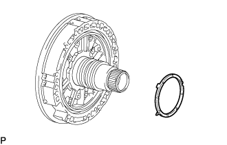
| 7. REMOVE CLUTCH DRUM THRUST WASHER |
Remove the clutch drum thrust washer from the stator shaft assembly.
| 8. INSPECT NO. 1 BRAKE PISTON RETURN SPRING SUB-ASSEMBLY |
Using a vernier caliper and straightedge, measure the distance between the No. 1 brake piston return spring sub-assembly end and the straightedge.
- Standard thickness:
- 5.72 mm (0.255 in.)
Text in Illustration*a
| Straightedge
|
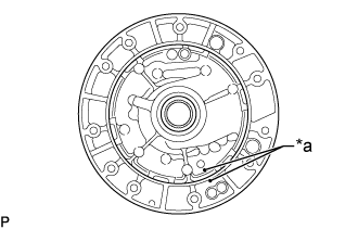
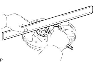
| 9. REMOVE STATOR SHAFT ASSEMBLY |
Put matchmarks on the stator shaft assembly and the front oil pump body sub-assembly.
Text in Illustration*a
| Matchmark
|
Using a T30 ''TORX'' socket wrench, remove the 8 bolts and stator shaft assembly from the front oil pump body sub-assembly.
| 10. REMOVE FRONT OIL PUMP BODY O-RING |
Remove the front oil pump body sub-assembly from the torque converter assembly.
Remove the front oil pump body O-ring from the front oil pump body sub-assembly.
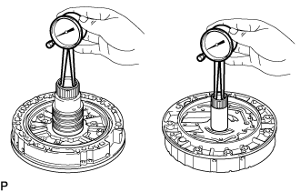
| 11. INSPECT STATOR SHAFT ASSEMBLY |
Using a caliper gauge, measure the inside diameter of the stator shaft assembly bushing.
- Maximum inside diameter:
- Front side:
- 25.926 mm (1.0207 in.)
- Rear side:
- 35.251 mm (1.3878 in.)
If the inside diameter is more than the maximum, replace the stator shaft assembly.
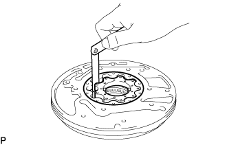
| 12. INSPECT CLEARANCE OF OIL PUMP ASSEMBLY |
Push the front oil pump driven gear to one side of the front oil pump body sub-assembly.
Using a feeler gauge, measure the clearance between the front oil pump driven gear and front oil pump body sub-assembly.
- Standard body clearance:
- 0.10 to 0.17 mm (0.00394 to 0.00669 in.)
If the body clearance is not as specified, replace the front oil pump drive gear, front oil pump driven gear and front oil pump body sub-assembly.
Using a feeler gauge, measure the clearance between the front oil pump driven gear teeth and front oil pump drive gear teeth.
- Standard tip clearance:
- 0.065 to 0.171 mm (0.00256 to 0.00673 in.)
If the tip clearance is not as specified, replace the front oil pump drive gear, front oil pump driven gear and front oil pump body sub-assembly.
|
Using a steel straightedge and feeler gauge, measure the clearance between both gears and the straightedge.
- Standard side clearance:
- 0.03 to 0.05 mm (0.00119 to 0.00196 in.)
If the side clearance is not as specified, replace the front oil pump drive gear, front oil pump driven gear and front oil pump body sub-assembly.
- HINT:
- There are 5 different thicknesses for the front oil pump drive gear and front oil pump driven gear.
- Front Oil Pump Drive Gear Thickness:
Part No.
| Mark
| Thickness
|
35321-60160
| A
| 12.590 to 12.599 mm (0.4957 to 0.4960 in.)
|
35321-60170
| B
| 12.600 to 12.609 mm (0.4961 to 0.4964 in.)
|
35321-60180
| C
| 12.610 to 12.620 mm (0.4965 to 0.4968 in.)
|
35321-60190
| D
| 12.621 to 12.630 mm (0.4969 to 0.4972 in.)
|
35321-60200
| E
| 12.631 to 12.640 mm (0.4973 to 0.4976 in.)
|
- Front Oil Pump Driven Gear Thickness:
Part No.
| Mark
| Thickness
|
35322-60160
| A
| 12.590 to 12.599 mm (0.4957 to 0.4960 in.)
|
35322-60170
| B
| 12.600 to 12.609 mm (0.4961 to 0.4964 in.)
|
35322-60180
| C
| 12.610 to 12.620 mm (0.4965 to 0.4968 in.)
|
35322-60190
| D
| 12.621 to 12.630 mm (0.4969 to 0.4972 in.)
|
35322-60200
| E
| 12.631 to 12.640 mm (0.4973 to 0.4976 in.)
|
| 13. REMOVE FRONT OIL PUMP DRIVE GEAR |
Remove the front oil pump drive gear.
| 14. REMOVE FRONT OIL PUMP DRIVEN GEAR |
Remove the front oil pump driven gear.
| 15. REMOVE FRONT OIL PUMP OIL SEAL |
Using a screwdriver, pry out the front oil pump oil seal.
Text in Illustration*a
| Protective Tape
|
- NOTICE:
- Be careful not to damage the front oil pump body sub-assembly.
- HINT:
- Wrap the tip of the screwdriver with protective tape.