Automatic Transmission Unit Disassembly
Drivetrain. Land Cruiser. Urj200, 202 Grj200 Vdj200
REMOVE TRANSMISSION BREATHER HOSE SUB-ASSEMBLY
REMOVE AUTOMATIC TRANSMISSION HOUSING
FIX AUTOMATIC TRANSMISSION ASSEMBLY
REMOVE REAR TRANSFER ADAPTER
REMOVE TRANSFER CASE ADAPTER REAR OIL SEAL
REMOVE PARK/NEUTRAL POSITION SWITCH ASSEMBLY
REMOVE OIL COOLER TUBE UNION
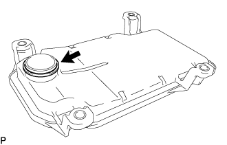
REMOVE REFILL PLUG
REMOVE AUTOMATIC TRANSMISSION CASE PLUG
REMOVE AUTOMATIC TRANSMISSION OIL PAN SUB-ASSEMBLY
REMOVE VALVE BODY OIL STRAINER ASSEMBLY
REMOVE TRANSMISSION VALVE BODY ASSEMBLY
REMOVE TRANSMISSION WIRE
REMOVE TRANSMISSION REVOLUTION SENSOR (SP2)
REMOVE PARKING LOCK PAWL BRACKET
REMOVE MANUAL VALVE LEVER SUB-ASSEMBLY
REMOVE PARKING LOCK ROD SUB-ASSEMBLY
REMOVE PARKING LOCK PAWL SHAFT
REMOVE MANUAL VALVE LEVER SHAFT OIL SEAL
REMOVE MANUAL DETENT SPRING SUB-ASSEMBLY
REMOVE OIL PUMP ASSEMBLY
REMOVE OVERDRIVE BRAKE PLATE STOPPER SPRING
REMOVE OVERDRIVE AND REVERSE MULTIPLE DISC CLUTCH ASSEMBLY AND FRONT PLANETARY GEAR ASSEMBLY WITH NO. 1 BRAKE DISC SET
REMOVE NO. 1 BRAKE DISC SET
INSPECT NO. 1 BRAKE DISC
REMOVE FRONT PLANETARY GEAR ASSEMBLY
INSPECT FRONT PLANETARY GEAR ASSEMBLY
REMOVE NO. 3 CLUTCH DISC SET
INSPECT NO. 3 CLUTCH DISC
REMOVE OVERDRIVE DIRECT CLUTCH DISC
INSPECT OVERDRIVE DIRECT CLUTCH DISC
REMOVE NO. 4 CLUTCH PISTON
INSPECT REVERSE CLUTCH RETURN SPRING SUB-ASSEMBLY (REAR)
REMOVE OVERDRIVE DIRECT CLUTCH DRUM SUB-ASSEMBLY
REMOVE REVERSE CLUTCH PISTON SUB-ASSEMBLY
INSPECT REVERSE CLUTCH RETURN SPRING SUB-ASSEMBLY (FRONT)
INSPECT REVERSE CLUTCH DRUM SUB-ASSEMBLY
REMOVE FORWARD MULTIPLE DISC CLUTCH ASSEMBLY WITH FRONT PLANETARY RING GEAR
REMOVE FRONT PLANETARY RING GEAR
REMOVE FORWARD MULTIPLE CLUTCH DISC SET
INSPECT FORWARD MULTIPLE CLUTCH DISC
REMOVE FORWARD CLUTCH PISTON
INSPECT FORWARD CLUTCH RETURN SPRING SUB-ASSEMBLY
INSPECT FORWARD CLUTCH DRUM SUB-ASSEMBLY
REMOVE FORWARD MULTIPLE DISC CLUTCH HUB
REMOVE SUN GEAR INPUT DRUM SUB-ASSEMBLY
INSPECT SUN GEAR INPUT DRUM SUB-ASSEMBLY
REMOVE REAR PLANETARY SUN GEAR SUB-ASSEMBLY
INSPECT REAR PLANETARY SUN GEAR SUB-ASSEMBLY
REMOVE ONE-WAY CLUTCH OUTER RACE WITH NO. 1 ONE-WAY CLUTCH
INSPECT NO. 1 ONE-WAY CLUTCH
REMOVE NO. 1 ONE-WAY CLUTCH
INSPECT REAR PLANETARY GEAR ASSEMBLY
REMOVE NO. 2 BRAKE DISC SET
INSPECT NO. 2 BRAKE DISC
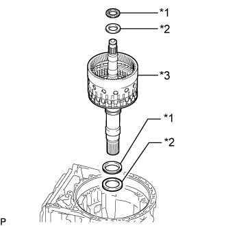
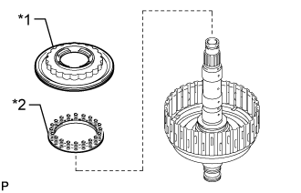
REMOVE DIRECT MULTIPLE DISC CLUTCH ASSEMBLY WITH REAR PLANETARY RING GEAR AND OUTPUT SHAFT SUB-ASSEMBLY
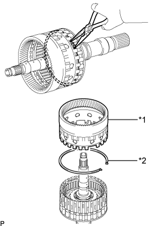
REMOVE REAR PLANETARY RING GEAR
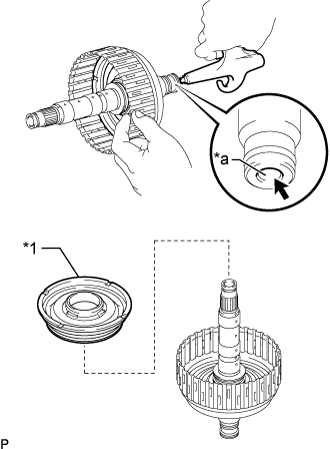
REMOVE DIRECT MULTIPLE DISC CLUTCH ASSEMBLY
REMOVE NO. 2 CLUTCH DISC SET
INSPECT NO. 2 CLUTCH DISC
REMOVE DIRECT CLUTCH PISTON
INSPECT DIRECT CLUTCH RETURN SPRING SUB-ASSEMBLY
REMOVE NO. 2 BRAKE PISTON
INSPECT NO. 2 BRAKE PISTON RETURN SPRING SUB-ASSEMBLY
REMOVE 1ST AND REVERSE BRAKE PLATE STOPPER SPRING
REMOVE OUTPUT SHAFT REAR RADIAL BALL BEARING
Automatic Transmission Unit -- Disassembly |
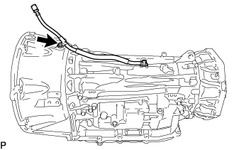
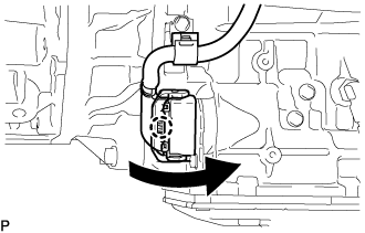
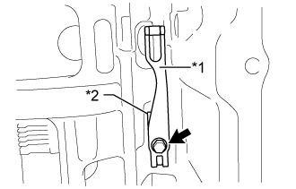
| 1. REMOVE TRANSMISSION BREATHER HOSE SUB-ASSEMBLY |
Remove the bolt and transmission breather hose sub-assembly from the automatic transmission case sub-assembly.
Remove the clamp from the breather plug hose.
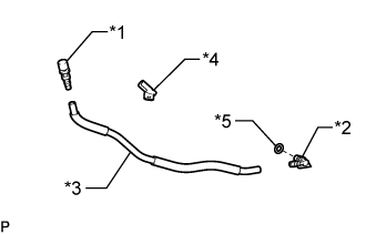
Text in Illustration*1
| No. 2 Breather Plug
|
*2
| No. 1 Breather Plug
|
*3
| Breather Plug Hose
|
*4
| Clamp
|
*5
| Breather Plug O-ring
|
Remove the No. 1 breather plug and No. 2 breather plug from the breather plug hose.
Remove the breather plug O-ring from the No. 1 breather plug.
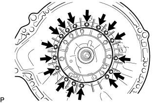
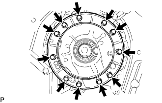
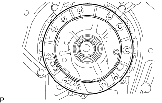
| 2. REMOVE AUTOMATIC TRANSMISSION HOUSING |
Remove the 16 bolts and automatic transmission housing from the automatic transmission case sub-assembly.
| 3. FIX AUTOMATIC TRANSMISSION ASSEMBLY |
Install the automatic transmission assembly to an overhaul attachment.
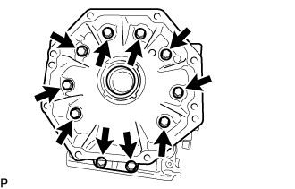
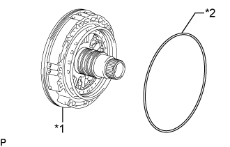
| 4. REMOVE REAR TRANSFER ADAPTER |
Remove the 10 bolts.
Remove the rear transfer adapter.
- HINT:
- Tap on the circumference of the rear transfer adapter with a plastic-faced hammer to remove the rear transfer adapter.
Remove the O-ring from the rear transfer adapter.
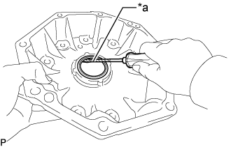
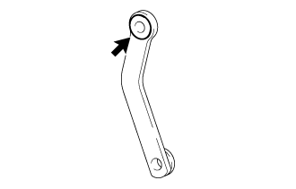
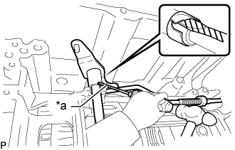
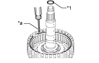
| 5. REMOVE TRANSFER CASE ADAPTER REAR OIL SEAL |
Using a screwdriver, pry out the transfer case adapter rear oil seal.
Text in Illustration*a
| Protective Tape
|
- NOTICE:
- Be careful not to damage the rear transfer adapter.
- HINT:
- Tape the screwdriver tip before use.
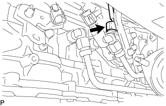
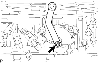
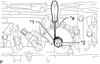
| 6. REMOVE PARK/NEUTRAL POSITION SWITCH ASSEMBLY |
Disconnect the switch connector.
Remove the nut, spring washer and transmission control shaft lever.
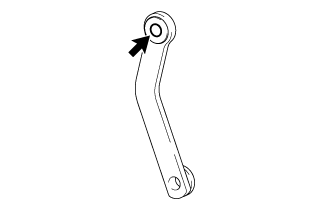
Remove the bush from the transmission control shaft lever.
Remove the No. 1 floor shift bush from the transmission control shaft lever.
Using a screwdriver, bend the tabs of the lock washer.
- HINT:
- Tape the screwdriver tip before use.
Text in Illustration*1
| Lock Washer
|
*2
| Lock Nut
|
*a
| Protective Tape
|
Remove the lock nut and lock washer.
Remove the 2 bolts and park/neutral position switch assembly.
- HINT:
- Make sure that the manual valve lever shaft has not been rotated prior to installing the park/neutral position switch assembly as the detent spring may become detached from the manual valve lever shaft.
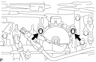
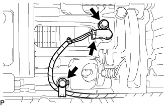
| 7. REMOVE OIL COOLER TUBE UNION |
Remove the 2 oil cooler tube unions from the automatic transmission case sub-assembly.
Remove the 2 O-rings from the 2 oil cooler tube unions.
Remove the refill plug from the automatic transmission case sub-assembly.
Remove the O-ring from the refill plug.
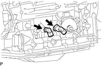
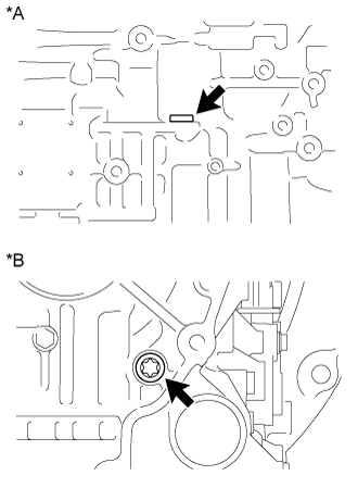
| 9. REMOVE AUTOMATIC TRANSMISSION CASE PLUG |
for T55H "TORX" Type:
Using a T55H "TORX" socket wrench, remove the 2 automatic transmission case plugs from the automatic transmission case sub-assembly.
Text in Illustration*A
| for LH Side
|
*B
| for Rear Side
|
Remove the 2 O-rings from the 2 automatic transmission case plugs.
for 17 mm Hexagon Type:
Remove the automatic transmission case plug from the automatic transmission case sub-assembly.
Remove the O-ring from the automatic transmission case plug.
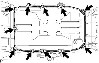
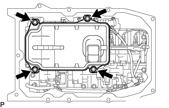
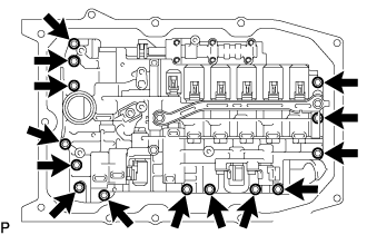
| 10. REMOVE AUTOMATIC TRANSMISSION OIL PAN SUB-ASSEMBLY |
Remove the 11 bolts, automatic transmission oil pan sub-assembly and automatic transmission oil pan gasket.
- NOTICE:
- Some fluid will remain in the automatic transmission oil pan sub-assembly. Remove all the pan bolts, and carefully remove the automatic transmission oil pan sub-assembly.
Remove the 4 transmission oil cleaner magnets from the automatic transmission oil pan sub-assembly.
Examine the particles in the automatic transmission oil pan sub-assembly.
Collect any steel chips with the removed transmission oil cleaner magnets. Carefully look at the foreign objects and particles in the automatic transmission oil pan sub-assembly and on the transmission oil cleaner magnets to guess the type of wear which might be found in the transmission.
Result:
Steel (magnetic): bearing, gear and clutch plate wear
Brass (non-magnetic): bush wear
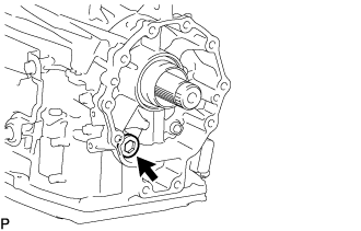
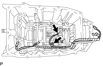
| 11. REMOVE VALVE BODY OIL STRAINER ASSEMBLY |
Remove the 4 bolts and valve body oil strainer assembly from the transmission valve body assembly.
- NOTICE:
- Be careful as some fluid will come out of the valve body oil strainer assembly.
Remove the O-ring from the valve body oil strainer assembly.
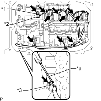
| 12. REMOVE TRANSMISSION VALVE BODY ASSEMBLY |
Remove the bolt, lock plate and ATF temperature sensor.
Text in Illustration*1
| Lock Plate
|
*2
| ATF Temperature Sensor
|
*3
| Transmission Revolution Sensor (NT) Connector
|
*a
| Protective Tape
|
Using a screwdriver, disconnect the transmission revolution sensor (NT) connector.
- HINT:
- Tape the screwdriver tip before use.
Disconnect the 9 connectors from the solenoid valves.
Remove the 14 bolts and transmission valve body assembly.
| 13. REMOVE TRANSMISSION WIRE |
Disconnect the connector from the transmission revolution sensor (SP2).
Remove the bolt and wire harness clamp.
Disconnect the transmission wire connector.
- HINT:
- Detach the claw, pull the lever, and then disconnect the transmission wire connector.
Remove the bolt and pull out the transmission wire.
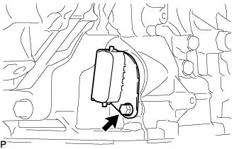
| 14. REMOVE TRANSMISSION REVOLUTION SENSOR (SP2) |
Remove the bolt and wire harness clamp.
Disconnect the connector from the transmission revolution sensor (SP2).
Remove the bolt and transmission revolution sensor (SP2) from the automatic transmission case sub-assembly.
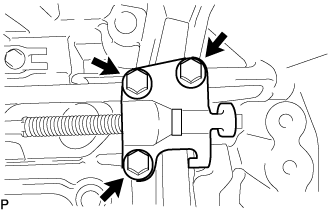
| 15. REMOVE PARKING LOCK PAWL BRACKET |
Remove the 3 bolts and parking lock pawl bracket.
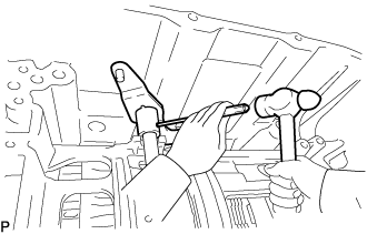
| 16. REMOVE MANUAL VALVE LEVER SUB-ASSEMBLY |
Using a screwdriver and hammer, cut off the spacer and remove it from the manual valve lever sub-assembly.
Text in Illustration*a
| Protective Tape
|
- NOTICE:
- Be careful not to damage the manual valve lever sub-assembly.
- HINT:
- Tape the screwdriver tip before use.
Using a 3 mm pin punch and a hammer, remove the spring pin.
- HINT:
- Slowly tap out the spring pin so that it does not fall into the automatic transmission case sub-assembly.
Remove the manual valve lever shaft and manual valve lever sub-assembly from the automatic transmission case sub-assembly.
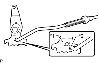
| 17. REMOVE PARKING LOCK ROD SUB-ASSEMBLY |
Remove the parking lock rod sub-assembly from the manual valve lever sub-assembly.
Text in Illustration*1
| Manual Valve Lever Sub-assembly
|
*2
| Parking Lock Rod Sub-assembly
|
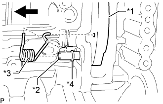
| 18. REMOVE PARKING LOCK PAWL SHAFT |
Remove the parking lock pawl shaft, parking lock pawl and spring.
Text in Illustration*1
| Parking Lock Pawl
|
*2
| Parking Lock Pawl Shaft
|
*3
| Spring
|
*4
| E-ring
|
Remove the E-ring from the parking lock pawl shaft.
| 19. REMOVE MANUAL VALVE LEVER SHAFT OIL SEAL |
Using a screwdriver, pry out the 2 manual valve lever shaft oil seals.
Text in Illustration*A
| for RH Side
|
*B
| for LH Side
|
*a
| Protective Tape
|
- NOTICE:
- Be careful not to damage the automatic transmission case sub-assembly.
- HINT:
- Tape the screwdriver tip before use.
| 20. REMOVE MANUAL DETENT SPRING SUB-ASSEMBLY |
Remove the bolt, manual detent spring sub-assembly and manual detent spring cover.
Text in Illustration*1
| Manual Detent Spring Sub-assembly
|
*2
| Manual Detent Spring Cover
|
| 21. REMOVE OIL PUMP ASSEMBLY |
Remove the 11 bolts from the oil pump assembly.
Pull out the oil pump assembly from the automatic transmission case sub-assembly.
- NOTICE:
- Do not damage the oil pump assembly.
Remove the oil pump O-ring from the oil pump assembly.
Text in Illustration*1
| Oil Pump Assembly
|
*2
| Oil Pump O-ring
|
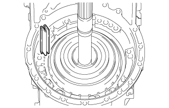
| 22. REMOVE OVERDRIVE BRAKE PLATE STOPPER SPRING |
Remove the overdrive brake plate stopper spring from the automatic transmission case sub-assembly.
| 23. REMOVE OVERDRIVE AND REVERSE MULTIPLE DISC CLUTCH ASSEMBLY AND FRONT PLANETARY GEAR ASSEMBLY WITH NO. 1 BRAKE DISC SET |
Remove the overdrive and reverse multiple disc clutch assembly and front planetary gear assembly with No. 1 brake disc set from the automatic transmission case sub-assembly.
Text in Illustration*1
| Overdrive and Reverse Multiple Disc Clutch Assembly and Front Planetary Gear Assembly with No. 1 Brake Disc Set
|
*2
| Thrust Needle Roller Bearing
|
*3
| Thrust Bearing Race
|
Remove the thrust needle roller bearing and thrust bearing race from the automatic transmission case sub-assembly.
Remove the snap ring from the automatic transmission case sub-assembly.
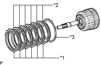
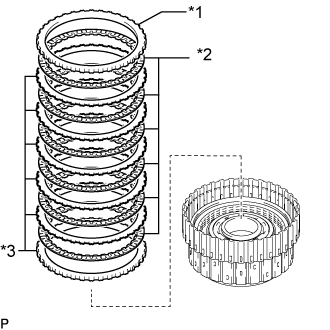
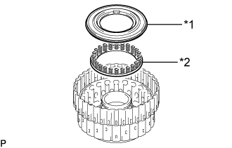
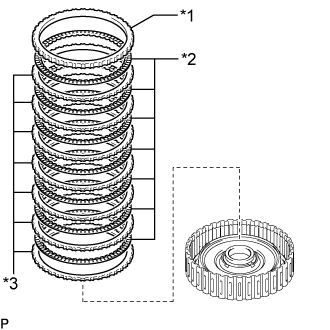
| 24. REMOVE NO. 1 BRAKE DISC SET |
Remove the 6 No. 1 brake plates, 6 No. 1 brake discs and No. 1 brake flange.
Text in Illustration*1
| No. 1 Brake Plate
|
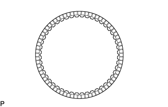
*2
| No. 1 Brake Disc
|
*3
| No. 1 Brake Flange
|
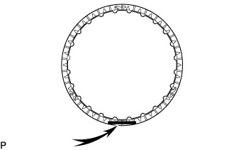
| 25. INSPECT NO. 1 BRAKE DISC |
Check whether the sliding surfaces of the No. 1 brake discs, No. 1 brake plates and the No. 1 brake flange are worn or burnt.
- NOTICE:
- If the linings of the No. 1 brake discs are peeled off or discolored, or if any part of the printed numbers is damaged, replace all the No. 1 brake discs.
- Before assembling new No. 1 brake discs, soak them in ATF for at least 2 hours.
If necessary, replace them.
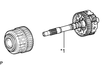
| 26. REMOVE FRONT PLANETARY GEAR ASSEMBLY |
Remove the front planetary gear assembly together with the planetary sun gear from the overdrive and reverse multiple disc clutch assembly.
Text in Illustration*1
| Front Planetary Gear Assembly
|
Remove the front planetary sun gear from the front planetary gear assembly.
Text in Illustration*1
| Front Planetary Sun Gear
|
Remove the planetary carrier thrust washer from the front planetary gear assembly.
Text in Illustration*1
| Planetary Carrier Thrust Washer
|
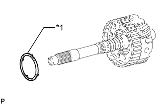
Remove the 3 oil seal rings from the front planetary gear assembly.
Text in Illustration*1
| Oil Seal Ring
|
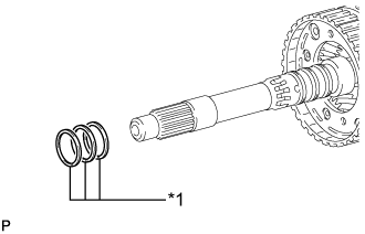
Remove the 2 oil seal rings from the front planetary gear assembly.
Text in Illustration*1
| Oil Seal Ring
|
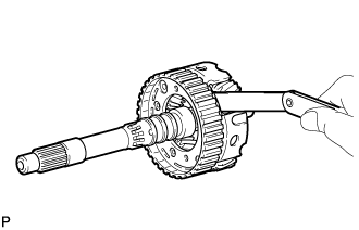
Remove the front planetary gear radial needle roller bearing from the front planetary gear assembly.
Text in Illustration*1
| Front Planetary Gear Radial Needle Roller Bearing
|
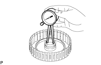
| 27. INSPECT FRONT PLANETARY GEAR ASSEMBLY |
Using a feeler gauge, measure the clearance between the front planetary gear assembly and each pinion gear.
- Standard Clearance:
- 0.2 to 0.6 mm (0.00788 to 0.0236 in.)
If the clearance is not as specified, replace the front planetary gear assembly.
| 28. REMOVE NO. 3 CLUTCH DISC SET |
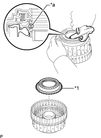
Using a screwdriver, remove the snap ring from the reverse clutch drum sub-assembly.
Text in Illustration*a
| Protective Tape
|
- NOTICE:
- Be careful not to damage the reverse clutch drum sub-assembly.
- HINT:
- Tape the screwdriver tip before use.
Remove the No. 3 clutch flange, 6 No. 3 clutch discs and 6 No. 3 clutch plates from the reverse clutch drum sub-assembly.
Text in Illustration*1
| No. 3 Clutch Flange
|
*2
| No. 3 Clutch Discs
|
*3
| No. 3 Clutch Plate
|
| 29. INSPECT NO. 3 CLUTCH DISC |
Check whether the sliding surfaces of the No. 3 clutch discs, No. 3 clutch plates and the No. 3 clutch flange are worn or burnt.
- NOTICE:
- If the linings of the No. 3 clutch discs are peeled off or discolored, or if any part of the printed numbers is damaged, replace all the No. 3 clutch discs.
- Before assembling new No. 3 clutch discs, soak them in ATF for at least 2 hours.
If necessary, replace them.
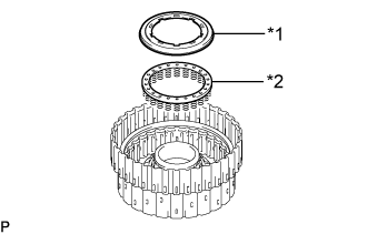
| 30. REMOVE OVERDRIVE DIRECT CLUTCH DISC |
Using a screwdriver, remove the snap ring from the overdrive direct clutch drum sub-assembly.
Text in Illustration*a
| Protective Tape
|
- NOTICE:
- Be careful not to damage the overdrive direct clutch drum sub-assembly.
- HINT:
- Tape the screwdriver tip before use.
Remove the overdrive clutch flange, 6 overdrive direct clutch discs and 6 overdrive direct clutch plates from the overdrive direct clutch drum sub-assembly.
Text in Illustration*1
| Overdrive Clutch Flange
|
*2
| Overdrive Direct Clutch Disc
|
*3
| Overdrive Direct Clutch Plate
|
| 31. INSPECT OVERDRIVE DIRECT CLUTCH DISC |
Check whether the sliding surfaces of the overdrive direct clutch discs, overdrive direct clutch plates and the overdrive clutch flange are worn or burnt.
- NOTICE:
- If the linings of the overdrive direct clutch discs are peeled off or discolored, or if any part of the printed numbers is damaged, replace all the overdrive direct clutch discs.
- Before assembling new overdrive direct clutch discs, soak them in ATF for at least 2 hours.
If necessary, replace them.
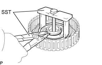
| 32. REMOVE NO. 4 CLUTCH PISTON |
Place SST on the reverse clutch balancer, and compress the reverse clutch return spring sub-assembly (rear) with a press.
- SST
- 09380-50010(09381-05020)
Using SST, remove the snap ring.
- SST
- 09350-30020(09350-07070)
Remove the reverse clutch balancer and reverse clutch return spring sub-assembly (rear) from the overdrive direct clutch drum sub-assembly.
Text in Illustration*1
| Reverse Clutch Balancer
|
*2
| Reverse Clutch Return Spring Sub-assembly (Rear)
|
While holding the overdrive direct clutch drum sub-assembly, apply compressed air to the oil hole to remove the No. 4 clutch piston.
Text in Illustration*1
| No. 4 Clutch Piston
|
*a
| Oil Hole
|
Remove the O-ring from the No. 4 clutch piston.
| 33. INSPECT REVERSE CLUTCH RETURN SPRING SUB-ASSEMBLY (REAR) |
Using a vernier caliper, measure the free length of the spring together with the spring seat.
- Standard Free Length:
- 22.21 mm (0.874 in.)
If the free length is shorter than the standard free length, replace the reverse clutch return spring sub-assembly (rear).
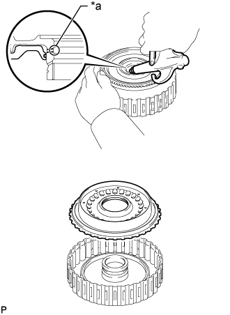
| 34. REMOVE OVERDRIVE DIRECT CLUTCH DRUM SUB-ASSEMBLY |
Remove the overdrive direct clutch drum sub-assembly from the reverse clutch drum sub-assembly.
Text in Illustration*1
| Snap Ring
|
*2
| Overdrive Direct Clutch Drum Sub-assembly
|
- HINT:
- If the overdrive direct clutch drum sub-assembly is difficult to remove, reinstall the snap ring for the overdrive direct clutch discs.
Remove the 3 O-rings from the overdrive direct clutch drum sub-assembly.
| 35. REMOVE REVERSE CLUTCH PISTON SUB-ASSEMBLY |
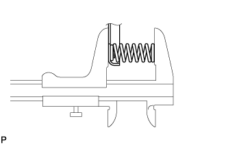
Place SST on the No. 3 clutch balancer, and compress the reverse clutch return spring sub-assembly (front) with a press.
- SST
- 09380-50010(09381-05020)
Using SST, remove the snap ring.
- SST
- 09350-30020(09350-07070)
Remove the No. 3 clutch balancer and reverse clutch return spring sub-assembly (front).
Text in Illustration*1
| No. 3 Clutch Balancer
|
*2
| Reverse Clutch Return Spring Sub-assembly (Front)
|
Remove the O-ring from the No. 3 clutch balancer.
Hold the reverse clutch drum sub-assembly and apply compressed air to the oil hole of the reverse clutch drum sub-assembly to remove the reverse clutch piston sub-assembly.
Text in Illustration*1
| Reverse Clutch Piston Sub-assembly
|
*a
| Oil Hole
|
Remove the O-ring from the reverse clutch piston sub-assembly.
Remove the O-ring from the reverse clutch drum sub-assembly.
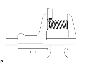
| 36. INSPECT REVERSE CLUTCH RETURN SPRING SUB-ASSEMBLY (FRONT) |
Using a vernier caliper, measure the free length of the spring together with the spring seat.
- Standard Free Length:
- 21.59 mm (0.850 in.)
If the free length is shorter than the standard free length, replace the reverse clutch return spring sub-assembly (front).
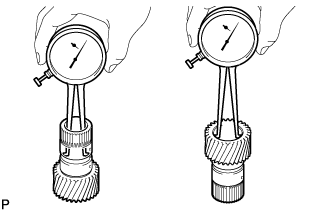
| 37. INSPECT REVERSE CLUTCH DRUM SUB-ASSEMBLY |
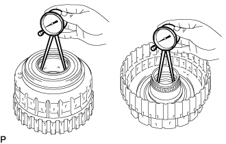
Using a caliper gauge, measure the inside diameter of the reverse clutch drum sub-assembly bush.
- Standard Inside Diameter (Front Side):
- 67.40 to 67.44 mm (2.6536 to 2.6551 in.)
- Standard Inside Diameter (Rear Side):
- 55.62 to 55.64 mm (2.1898 to 2.1905 in.)
If the inside diameter is not as specified, replace the reverse clutch drum sub-assembly.
| 38. REMOVE FORWARD MULTIPLE DISC CLUTCH ASSEMBLY WITH FRONT PLANETARY RING GEAR |
Remove the forward multiple disc clutch assembly with front planetary ring gear, thrust needle roller bearing and thrust bearing race from the automatic transmission case sub-assembly.
Text in Illustration*1
| Forward Multiple Disc Clutch Assembly with Front Planetary Ring Gear
|
*2
| Thrust Needle Roller Bearing
|
*3
| Thrust Bearing Race
|
| 39. REMOVE FRONT PLANETARY RING GEAR |
Using needle-nose pliers, detach the snap ring and remove the front planetary ring gear and snap ring from the forward multiple disc clutch assembly.
Text in Illustration*1
| Front Planetary Ring Gear
|
*2
| Snap Ring
|
*3
| Forward Multiple Disc Clutch Assembly
|
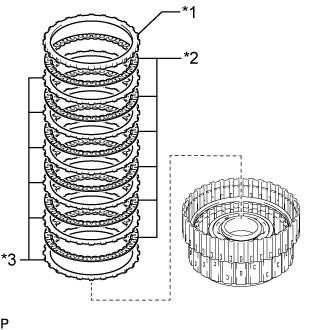
| 40. REMOVE FORWARD MULTIPLE CLUTCH DISC SET |
Using a screwdriver, remove the snap ring.
Text in Illustration*a
| Protective Tape
|
- NOTICE:
- Be careful not to damage the forward multiple clutch disc assembly.
- HINT:
- Tape the screwdriver tip before use.
Remove the forward clutch flange, 7 forward multiple clutch discs and 7 forward multiple clutch plates.
Text in Illustration*1
| Forward Clutch Flange
|
*2
| Forward Multiple Clutch Disc
|
*3
| Forward Multiple Clutch Plate
|
| 41. INSPECT FORWARD MULTIPLE CLUTCH DISC |
Check whether the sliding surfaces of the forward multiple clutch discs, forward multiple clutch plates and forward clutch flange are worn or burnt.
- NOTICE:
- If the linings of the forward multiple clutch discs are peeled off or discolored, replace all the forward multiple clutch discs.
- Before assembling new forward multiple clutch discs, soak them in ATF for at least 2 hours.
If necessary, replace them.
| 42. REMOVE FORWARD CLUTCH PISTON |
Place SST on the No. 1 clutch balancer, and compress the forward clutch return spring sub-assembly with a press.
- SST
- 09380-50010(09381-05020)
Using SST, remove the snap ring.
- SST
- 09350-30020(09350-07070)
Remove the No. 1 clutch balancer and forward clutch return spring sub-assembly from the forward clutch drum sub-assembly.
Text in Illustration*1
| No. 1 Clutch Balancer
|
*2
| Forward Clutch Return Spring Sub-assembly
|
Remove the O-ring from the No. 1 clutch balancer.
Hold the forward clutch drum sub-assembly and apply compressed air to the oil hole of the forward clutch drum sub-assembly to remove the forward clutch piston.
Text in Illustration*a
| Oil Hole
|
Remove the 2 O-rings from the forward clutch piston.
| 43. INSPECT FORWARD CLUTCH RETURN SPRING SUB-ASSEMBLY |
Using a vernier caliper, measure the free length of the spring together with the spring seat.
- Standard Free Length:
- 20.82 mm (0.820 in.)
If the free length is shorter than the standard free length, replace the forward clutch return spring sub-assembly.
| 44. INSPECT FORWARD CLUTCH DRUM SUB-ASSEMBLY |
Using a caliper gauge, measure the inside diameter of the forward clutch drum bush.
- Standard Inside Diameter:
- 33.200 to 33.225 mm (1.3071 to 1.3080 in.)
If the inside diameter is not as specified, replace the forward clutch drum sub-assembly.
| 45. REMOVE FORWARD MULTIPLE DISC CLUTCH HUB |
Remove the forward multiple disc clutch hub from the automatic transmission case sub-assembly.
Text in Illustration*1
| Forward Multiple Disc Clutch Hub
|
*2
| Thrust Bearing Race
|
*3
| Thrust Needle Roller Bearing
|
Remove the thrust bearing race and thrust needle roller bearing from the automatic transmission case sub-assembly.
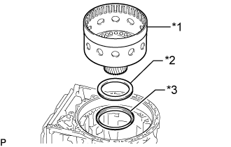
| 46. REMOVE SUN GEAR INPUT DRUM SUB-ASSEMBLY |
Remove the sun gear input drum sub-assembly, thrust needle roller bearing and thrust bearing race from the automatic transmission case sub-assembly.
Text in Illustration*1
| Sun Gear Input Drum Sub-assembly
|
*2
| Thrust Needle Roller Bearing
|
*3
| Thrust Bearing Race
|
| 47. INSPECT SUN GEAR INPUT DRUM SUB-ASSEMBLY |
Using a caliper gauge, measure the inside diameter of the sun gear input drum bush.
- Standard Inside Diameter:
- 45.066 to 45.091 mm (1.7743 to 1.7752 in.)
If the inside diameter is not as specified, replace the sun gear input drum sub-assembly.
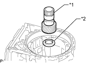
| 48. REMOVE REAR PLANETARY SUN GEAR SUB-ASSEMBLY |
Remove the rear planetary sun gear sub-assembly and thrust bearing race from the automatic transmission case sub-assembly.
Text in Illustration*1
| Rear Planetary Sun Gear Sub-assembly
|
*2
| Thrust Bearing Race
|
| 49. INSPECT REAR PLANETARY SUN GEAR SUB-ASSEMBLY |
Using a caliper gauge, measure the inside diameter of the rear planetary sun gear bush.
- Standard Inside Diameter:
- 28.760 to 28.781 mm (1.1323 to 1.1331 in.)
If the inside diameter is not as specified, replace the rear planetary sun gear sub-assembly.
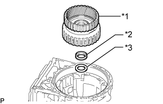
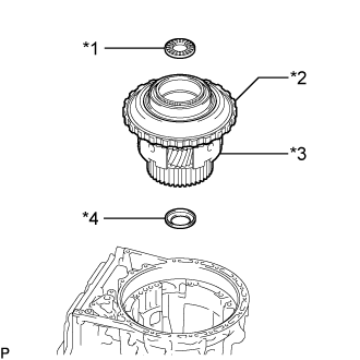
| 50. REMOVE ONE-WAY CLUTCH OUTER RACE WITH NO. 1 ONE-WAY CLUTCH |
Using SST, remove the snap ring from the automatic transmission case sub-assembly.
- SST
- 09350-30020(09350-07060)
Remove the thrust needle roller bearing, rear planetary gear assembly, one-way clutch outer race with No. 1 one-way clutch and thrust bearing race from the automatic transmission case sub-assembly.
Text in Illustration*1
| Thrust Needle Roller Bearing
|
*2
| One-way Clutch Outer Race with No. 1 One-way Clutch
|
*3
| Rear Planetary Gear Assembly
|
*4
| Thrust Bearing Race
|
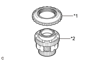
Remove the one-way clutch outer race with No. 1 one-way clutch from the rear planetary gear assembly.
Text in Illustration*1
| One-way Clutch Outer Race with No. 1 One-way Clutch
|
*2
| Rear Planetary Gear Assembly
|
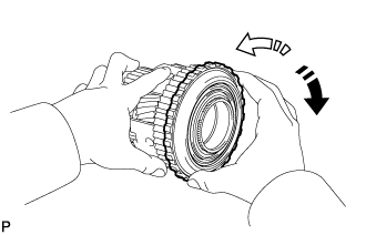
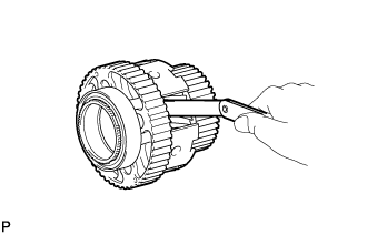
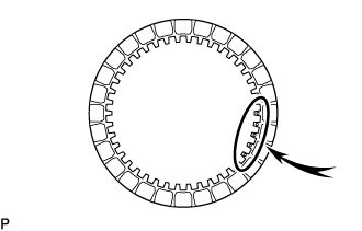
| 51. INSPECT NO. 1 ONE-WAY CLUTCH |
Install the No. 1 one-way clutch to the rear planetary gear assembly.
Hold the rear planetary gear assembly and turn the No. 1 one-way clutch.
Text in Illustration
| Lock
|

| Free
|
Check that the No. 1 one-way clutch turns freely counterclockwise and locks clockwise.
If the No. 1 one-way clutch does not operate normally, replace it.
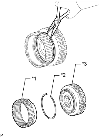
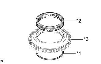
| 52. REMOVE NO. 1 ONE-WAY CLUTCH |
Remove the snap ring and No. 1 one-way clutch from the one-way clutch outer race.
Text in Illustration*1
| Snap Ring
|
*2
| No. 1 One-way Clutch
|
*3
| One-way Clutch Outer Race
|
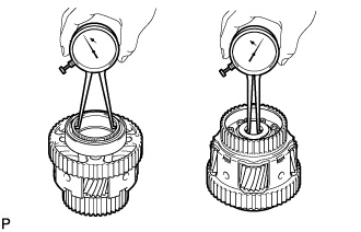
| 53. INSPECT REAR PLANETARY GEAR ASSEMBLY |
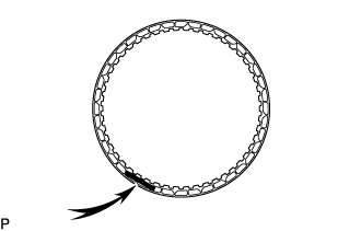
Using a feeler gauge, measure the rear planetary gear pinion long and short thrust clearance.
- Standard Clearance:
- 0.2 to 0.6 mm (0.00788 to 0.0236 in.)
If the clearance is not as specified, replace the rear planetary gear assembly.
Using a caliper gauge, measure the inside diameter of the rear planetary gear bush.
- Standard Inside Diameter (Front Side):
- 70.60 to 70.63 mm (2.7796 to 2.7807 in.)
- Standard Inside Diameter (Rear Side):
- 28.700 to 28.721 mm (1.1300 to 1.1307 in.)
If the inside diameter is not as specified, replace the rear planetary gear assembly.
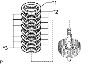
| 54. REMOVE NO. 2 BRAKE DISC SET |
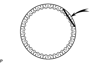
Remove the snap ring from the automatic transmission case sub-assembly.
Remove the brake plate, 6 No. 2 brake discs, 5 No. 2 brake plates and No. 2 brake flange from the automatic transmission case sub-assembly.
Text in Illustration*1
| Brake Plate
|
*2
| No. 2 Brake Disc
|
*3
| No. 2 Brake Plate
|
*4
| No. 2 Brake Flange
|
| 55. INSPECT NO. 2 BRAKE DISC |
Check whether the sliding surfaces of the No. 2 brake discs, brake plate, No. 2 brake plates and the No. 2 brake flange are worn or burnt.
- NOTICE:
- If the linings of the No. 2 brake discs are peeled off or discolored, or if any part of the printed numbers is damaged, replace all the No. 2 brake discs.
- Before assembling new discs, soak them in ATF for at least 2 hours.
If necessary, replace them.
| 56. REMOVE DIRECT MULTIPLE DISC CLUTCH ASSEMBLY WITH REAR PLANETARY RING GEAR AND OUTPUT SHAFT SUB-ASSEMBLY |
Remove the 2 thrust needle roller bearings, 2 thrust bearing races and direct multiple disc clutch assembly with rear planetary ring gear and output shaft sub-assembly from the automatic transmission case sub-assembly.
Text in Illustration*1
| Thrust Needle Roller Bearing
|
*2
| Thrust Bearing Race
|
*3
| Direct Multiple Disc Clutch Assembly with Rear Planetary Ring Gear and Output Shaft Sub-assembly
|
| 57. REMOVE REAR PLANETARY RING GEAR |
Using needle-nose pliers, detach the snap ring and remove the rear planetary ring gear from the output shaft sub-assembly.
Text in Illustration*1
| Rear Planetary Ring Gear
|
*2
| Snap Ring
|
| 58. REMOVE DIRECT MULTIPLE DISC CLUTCH ASSEMBLY |
Remove the direct multiple disc clutch assembly from the output shaft sub-assembly.
Text in Illustration*1
| Direct Multiple Disc Clutch Assembly
|
*2
| Thrust Needle Roller Bearing
|
*3
| Thrust Bearing Race
|
*4
| Output Shaft Sub-assembly
|
Remove the thrust needle roller bearing and 2 thrust bearing races from the output shaft sub-assembly.
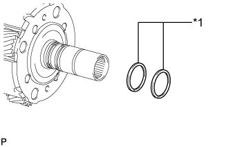
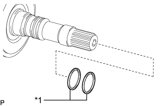
Remove the 2 oil seal ring from the output shaft sub-assembly.
Text in Illustration*1
| Oil Seal Ring
|
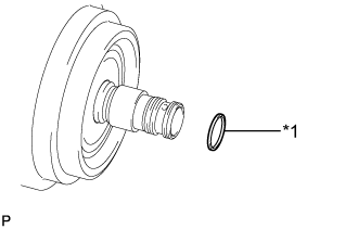
Remove the oil seal ring from the direct multiple disc clutch assembly.
Text in Illustration*1
| Oil Seal Ring
|
| 59. REMOVE NO. 2 CLUTCH DISC SET |
Remove the oil seal ring from the direct multiple disc clutch assembly.
Text in Illustration*1
| Oil Seal Ring
|
*a
| Protective Tape
|
Using a screwdriver, remove the snap ring from the direct clutch drum sub-assembly.
- NOTICE:
- Be careful not to damage the direct clutch drum sub-assembly.
- HINT:
- Tape the screwdriver tip before use.
Remove the No. 2 clutch flange, 7 No. 2 clutch discs and 7 No. 2 clutch plates from the direct clutch drum sub-assembly.
Text in Illustration*1
| No. 2 Clutch Flange
|
*2
| No. 2 Clutch Disc
|
*3
| No. 2 Clutch Plate
|
| 60. INSPECT NO. 2 CLUTCH DISC |
Check whether the sliding surfaces of the No. 2 clutch discs, No. 2 clutch plates and the No. 2 clutch flange are worn or burnt.
- NOTICE:
- If the linings of the No. 2 clutch discs are peeled off or discolored, replace all the No. 2 clutch discs.
- Before assembling new discs, soak them in ATF for at least 2 hours.
If necessary, replace them.
| 61. REMOVE DIRECT CLUTCH PISTON |
Place SST on the No. 2 clutch balancer, and compress the direct clutch return spring sub-assembly with a press.
- SST
- 09387-00020
Using SST, remove the snap ring.
- SST
- 09350-30020(09350-07070)
Remove the No. 2 clutch balancer and direct clutch return spring sub-assembly from the direct clutch drum sub-assembly.
Text in Illustration*1
| No. 2 Clutch Balancer
|
*2
| Direct Clutch Return Spring Sub-assembly
|
Remove the O-ring from the No. 2 clutch balancer.
Hold the direct clutch drum sub-assembly and apply compressed air to the oil hole of the direct clutch drum sub-assembly to remove the direct clutch piston.
Text in Illustration*1
| Direct Clutch Piston
|
*a
| Oil Hole
|
Remove the O-ring from the direct clutch piston.
Remove the O-ring from the direct clutch drum sub-assembly.
| 62. INSPECT DIRECT CLUTCH RETURN SPRING SUB-ASSEMBLY |
Using a vernier caliper, measure the free length of the spring together with the spring seat.
- Standard Free Length:
- 20.76 mm (0.817 in.)
If the free length is shorter than the standard free length, replace the direct clutch return spring sub-assembly.
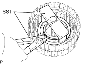
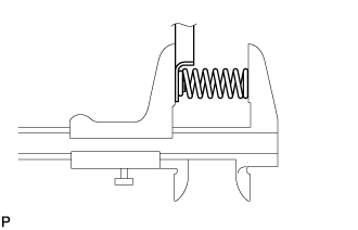
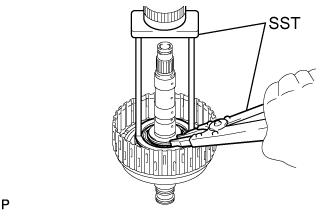
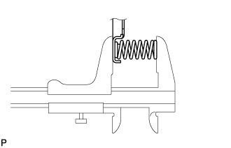
| 63. REMOVE NO. 2 BRAKE PISTON |
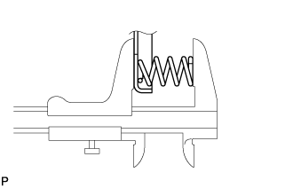
Set SST on the No. 2 brake piston return spring sub-assembly, tighten SST and compress the No. 2 brake piston return spring sub-assembly.
- SST
- 09380-50010(09381-05010,09381-05020,09381-05030,09381-05040,09381-05050)
Text in Illustration*1
| No. 2 Brake Piston Return Spring Sub-assembly
|
*2
| Snap Ring
|
Using SST, remove the snap ring and the No. 2 brake piston return spring sub-assembly.
- SST
- 09350-30020(09350-07070)
Apply compressed air to the oil hole of the automatic transmission case sub-assembly to remove the No. 2 brake piston from the automatic transmission case sub-assembly.
Text in Illustration*a
| Oil Hole
|
Remove the 3 O-rings from the No. 2 brake piston.
| 64. INSPECT NO. 2 BRAKE PISTON RETURN SPRING SUB-ASSEMBLY |
Using a vernier caliper, measure the free length of the spring together with the spring seat.
- Standard Free Length:
- 23.36 mm (0.920 in.)
If the free length is shorter than the standard free length, replace the No. 2 brake piston return spring sub-assembly.
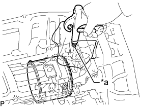
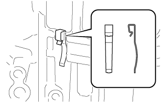
| 65. REMOVE 1ST AND REVERSE BRAKE PLATE STOPPER SPRING |
Remove the 1st and reverse brake plate stopper spring from the automatic transmission case sub-assembly.
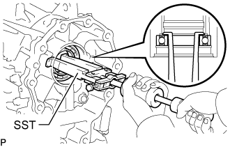
| 66. REMOVE OUTPUT SHAFT REAR RADIAL BALL BEARING |
Using snap ring pliers, remove the snap ring from the automatic transmission case sub-assembly.
Using SST, remove the output shaft rear radial ball bearing.
- SST
- 09308-00010