READ VALUE USING GTS (SPD (NT) AND NT SENSOR VOLTAGE)
CHECK TRANSMISSION REVOLUTION SENSOR TERMINAL (NT TERMINAL)
INSPECT TRANSMISSION WIRE (TRANSMISSION REVOLUTION SENSOR (NT))
CHECK HARNESS AND CONNECTOR (TRANSMISSION WIRE - TCM)
DTC P0717 Input/Turbine Speed Sensor "A" Circuit No Signal |
DTC P07BF Input/Turbine Speed Sensor "A" Circuit Low |
DTC P07C0 Input/Turbine Speed Sensor "A" Circuit High |
DESCRIPTION
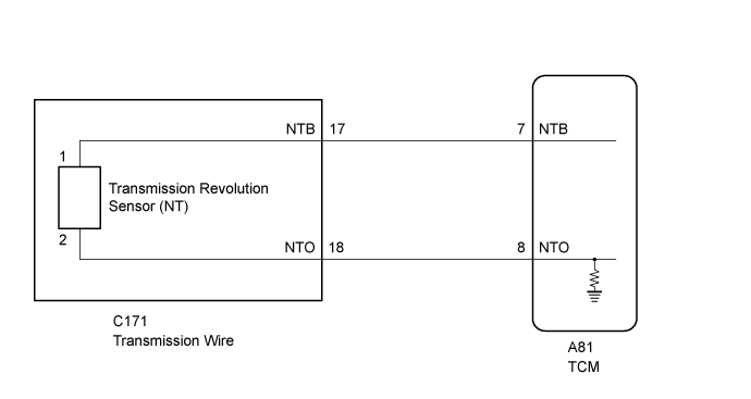
The transmission revolution sensor (NT) detects the input shaft rotation speed and sends it to the TCM.Based on the transmission revolution sensor (NT) signal and the transmission revolution sensor (SP2) signals, the TCM controls engine torque and shift timing. Based on the input shaft rotation speed and the engine speed signal, lock-up control is performed.
| DTC No. | DTC Detection Condition
| Trouble Area |
| P0717 |
|
|
| P07BF |
| |
| P07C0 |
|
MONITOR DESCRIPTION
The transmission revolution sensor (NT) detects the input shaft speed. The TCM calculates gear shifts comparing the transmission revolution sensor (NT) with the transmission revolution sensor (SP2).If the TCM detects no signal from the transmission revolution sensor (NT) even while the vehicle is moving, it will conclude that is a malfunction of the transmission revolution sensor (NT). The TCM will illuminate the MIL and store a DTC.
WIRING DIAGRAM
INSPECTION PROCEDURE
- NOTICE:
- Perform registration and/or initialization when parts related to the automatic transmission are replaced (Click here).
- HINT:
- After performing repair, clear the DTCs and perform the following procedure to check that DTCs are not output.
- Perform the D Position Shift Test inspection in Road Test (Click here).
- Check for DTCs again (Click here).
| DATA LIST |
- NOTICE:
- In the table below, the values listed under "Normal Condition" are reference values. Do not depend solely on these reference values when deciding whether a part is faulty or not.
- HINT:
- Using the GTS to read the Data List allows the values or states of switches, sensors, actuators and other items to be read without removing any parts. This non-intrusive inspection can be very useful because intermittent conditions or signals may be discovered before parts or wiring is disturbed. Reading the Data List information early in troubleshooting is one way to save diagnostic time.
Warm up the engine.
Turn the engine switch off.
Connect the GTS to the DLC3.
Turn the engine switch on (IG).
Turn the GTS on.
Enter the following menus: Powertrain / ECT / Data List / SPD (NT).
According to the display on the GTS, read the Data List.
ECT Tester Display Measurement Item/Range Normal Condition Diagnostic Note SPD (NT) Input shaft speed/
Min.: 0 rpm
Max.: 12750 rpm- Equal to engine speed: Lock-up on (after warming up engine)
- Nearly equal to engine speed: Lock-up off (idling with shift lever in N)
Data is displayed in increments of 50 rpm. - HINT:
- SPD (NT) is always 0 while driving: Open or short in the sensor or circuit.
- SPD (NT) is always more than 0 and less than 300 rpm while driving the vehicle at 50 km/h (31 mph) or more: Sensor malfunction, improper installation, or intermittent connection malfunction in the circuit.
- Equal to engine speed: Lock-up on (after warming up engine)
| 1.READ VALUE USING GTS (SPD (NT) AND NT SENSOR VOLTAGE) |
Turn the engine switch off.
Connect the GTS to the DLC3.
Turn the engine switch on (IG).
Turn the GTS on.
Enter the following menus: Powertrain / ECT / Data List / SPD (NT), NT Sensor Voltage.
According to the display on the GTS, read the Data List.
ECT Tester Display Measurement Item/Range Normal Condition Diagnostic Note SPD (NT) Input shaft speed/
Min.: 0 rpm
Max.: 12750 rpm- Equal to engine speed: Lock-up on (after warming up engine)
- Nearly equal to engine speed: Lock-up off (idling with shift lever in N)
Data is displayed in increments of 50 rpm. NT Sensor Voltage NT sensor voltage/
Min.: 0 V
Max.: 5 V- 1.182 to 1.622 V: High current
- 0.391 to 0.814 V: Low current
- Result Result Proceed to Data List value is not within the normal condition A Data List value is within the normal condition B - Equal to engine speed: Lock-up on (after warming up engine)
|
| ||||
| A | |
| 2.CHECK TRANSMISSION REVOLUTION SENSOR TERMINAL (NT TERMINAL) |
Disconnect the transmission wire connector.
 |
Turn the engine switch on (IG).
Measure the voltage according to the value(s) in the table below.
- Standard Voltage:
Tester Connection Switch Condition Specified Condition C171-17 (NTB) - Body ground Engine switch on (IG) 11 to 14 V
Turn the engine switch off.
Measure the resistance according to the value(s) in the table below.
- Standard Resistance:
Tester Connection Condition Specified Condition C171-18 (NTO) - Body ground Always 99 to 101 Ω
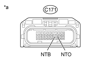
| *a | Front view of wire harness connector (to Transmission Wire) |
|
| ||||
| OK | |
| 3.INSPECT TRANSMISSION WIRE (TRANSMISSION REVOLUTION SENSOR (NT)) |
Disconnect the transmission revolution sensor (NT) connector (Click here).
 |
Disconnect the transmission wire connector.
Measure the resistance according to the value(s) in the table below.
- Standard Resistance:
Tester Connection Condition Specified Condition Terminal 1 of the transmission revolution sensor (NT) connector - 17 (NTB) Always Below 1 Ω Terminal 2 of the transmission revolution sensor (NT) connector - 18 (NTO) Always Below 1 Ω Terminal 1 of the transmission revolution sensor (NT) connector or 17 (NTB) - Body ground Always 10 kΩ or higher Terminal 2 of the transmission revolution sensor (NT) connector or 18 (NTO) - Body ground Always 10 kΩ or higher
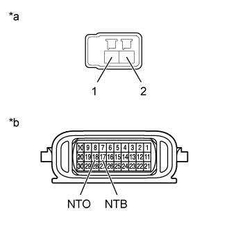
Text in Illustration *a Front view of wire harness connector
(to Transmission Revolution Sensor (NT))*b Component without harness connected
(Transmission Wire)
|
| ||||
| OK | ||
| ||
| 4.CHECK HARNESS AND CONNECTOR (TRANSMISSION WIRE - TCM) |
Disconnect the C171 transmission wire connector.
Disconnect the A81 TCM connector.
Measure the resistance according to the value(s) in the table below.
- Standard Resistance:
Tester Connection Condition Specified Condition C171-17 (NTB) - A81-7 (NTB) Always Below 1 Ω C171-18 (NTO) - A81-8 (NTO) Always Below 1 Ω C171-17 (NTB) or A81-7 (NTB) - Body ground Always 10 kΩ or higher C171-18 (NTO) or A81-8 (NTO) - Body ground Always 10 kΩ or higher
|
| ||||
| OK | ||
| ||