Land Cruiser URJ200 URJ202 GRJ200 VDJ200 - 1UR-FE ENGINE CONTROL
READ VALUE USING GTS (STOP LIGHT SWITCH)
INSPECT STOP LIGHT SWITCH ASSEMBLY (B+ VOLTAGE)
INSPECT STOP LIGHT SWITCH ASSEMBLY
INSPECT ECM (STP AND ST1 - VOLTAGE)
DTC P0504 Brake Switch "A" / "B" Correlation
DESCRIPTION
The stop light switch is a duplex system that transmits two signals: STP and ST1-. These two signals are used by the ECM to monitor whether or not the brake system is working properly. If signals which indicate the brake pedal is being depressed and released are detected simultaneously, the ECM interprets this as a malfunction in the stop light switch and stores the DTC.
- HINT:
- The normal signal conditions are as shown in the table below.
| Signal (ECM Terminal) | Brake Pedal Released | In Transition | Brake Pedal Depressed |
| STP | OFF | ON | ON |
| ST1- | ON | ON | OFF |
| DTC No. | DTC Detection Condition | Trouble Area |
| P0504 | Conditions (a), (b) and (c) continue for 0.5 seconds or more (1 trip detection logic): (a) Engine switch is on (IG). (b) Brake pedal is released. (c) STP signal is OFF when the ST1- signal is OFF. | Short in stop light switch signal circuit STOP fuse IGN fuse Stop light switch assembly ECM |
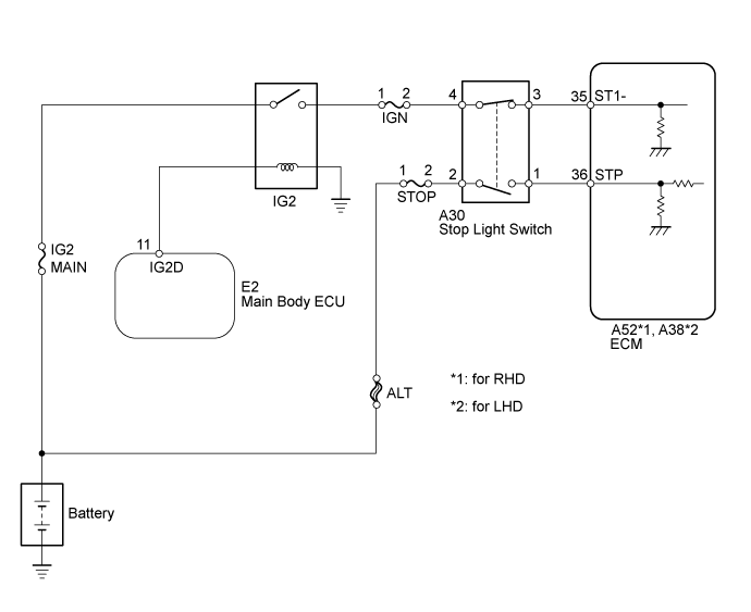
WIRING DIAGRAM
INSPECTION PROCEDURE
- NOTICE:
- Inspect the fuses of circuits related to this system before performing the following inspection procedure.
- HINT:
| Brake Pedal Operation | Specified Condition |
| Depressed | STP signal ON |
| Released | STP signal OFF |
| 1.READ VALUE USING GTS (STOP LIGHT SWITCH) |
Connect the GTS to the DLC3.
Turn the engine switch on (IG).
Turn the GTS on.
Enter the following menus: Powertrain / Engine and ECT / All Data / Stop Light Switch.
Read the value displayed on the GTS.
- Standard:
Condition Specified Condition Brake pedal depressed STP signal ON Brake pedal released STP signal OFF
|
| ||||
| OK | ||
| ||
| 2.INSPECT STOP LIGHT SWITCH ASSEMBLY (B+ VOLTAGE) |

Disconnect the stop light switch connector.
Measure the voltage according to the value(s) in the table below.
- Standard Voltage:
Tester Connection Condition Specified Condition A30-2 - Body ground Always 11 to 14 V A30-4 - Body ground Engine switch on (IG) 11 to 14 V
| *a | Front view of wire harness connector (to Stop Light Switch) |
|
| ||||
| OK | |
| 3.INSPECT STOP LIGHT SWITCH ASSEMBLY |
Inspect the stop light switch assembly ().
|
| ||||
| OK | |
| 4.INSPECT ECM (STP AND ST1 - VOLTAGE) |
Disconnect the ECM connector.
Turn the engine switch on (IG).
Measure the voltage according to the value(s) in the table below.
- Standard Voltage:
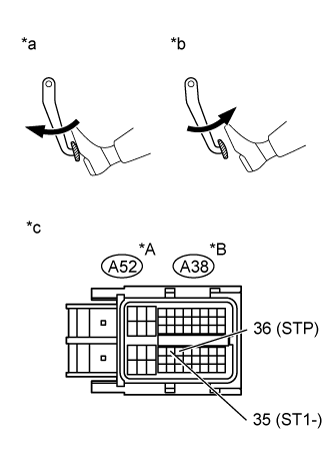
for RHD Tester Connection Condition Specified Condition A52-35 (ST1-) - Body ground Brake pedal released 7.5 to 14 V Brake pedal depressed Below 1.5 V A52-36 (STP) - Body ground Brake pedal released Below 1.5 V Brake pedal depressed 7.5 to 14 V for LHD Tester Connection Condition Specified Condition A38-35 (ST1-) - Body ground Brake pedal released 7.5 to 14 V Brake pedal depressed Below 1.5 V A38-36 (STP) - Body ground Brake pedal released Below 1.5 V Brake pedal depressed 7.5 to 14 V
| *A | for RHD |
| *B | for LHD |
| *a | Depressed |
| *b | Released |
| *c | Component with harness connected (ECM) |
|
| ||||
| OK | ||
| ||