Land Cruiser URJ200 URJ202 GRJ200 VDJ200 - 1GR-FE ENGINE CONTROL
CHECK FOR ANY OTHER DTCS OUTPUT (IN ADDITION TO DTC P2A00 AND/OR P2A03)
INSPECT AIR FUEL RATIO SENSOR (HEATER RESISTANCE)
CHECK HARNESS AND CONNECTOR (AIR FUEL RATIO SENSOR - ECM)
PERFORM CONFIRMATION DRIVING PATTERN
CHECK WHETHER DTC OUTPUT RECURS (DTC P2A00 AND/OR P2A03)
PERFORM CONFIRMATION DRIVING PATTERN
CHECK WHETHER DTC OUTPUT RECURS (DTC P2A00 AND/OR P2A03)
DTC P2A00 A/F Sensor Circuit Slow Response (Bank 1 Sensor 1)
DTC P2A03 A/F Sensor Circuit Slow Response (Bank 2 Sensor 1)
DESCRIPTION
Refer to DTC P2195 ().
- HINT:
| DTC No. | DTC Detection Condition | Trouble Area |
| P2A00 P2A03 | The calculated value for the air fuel ratio sensor response rate deterioration level is less than the threshold (2 trip detection logic). | Open or short in air fuel ratio sensor (bank 1, 2 sensor 1) circuit Air fuel ratio sensor Air fuel ratio sensor heater ECM |
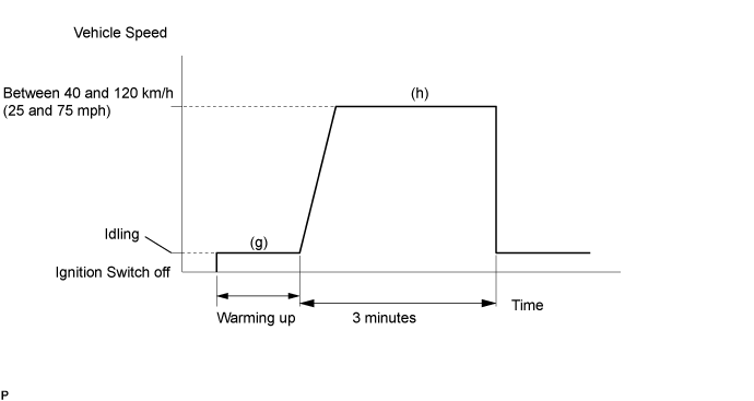
CONFIRMATION DRIVING PATTERN
- HINT:
- Performing this confirmation driving pattern will activate the air fuel ratio sensor response monitor.
WIRING DIAGRAM
Refer to DTC P2195 ().
INSPECTION PROCEDURE
- HINT:
- Malfunctioning areas can be identified by performing the Control the Injection Volume for A/F Sensor function provided in the Active Test. The Control the Injection Volume for A/F Sensor function can help to determine whether the air fuel ratio sensor, heated oxygen sensor and other potential trouble areas are malfunctioning.
- The following instructions describe how to conduct the Control the Injection Volume for A/F Sensor operation using the GTS.
- HINT:
| GTS Display (Sensor) | Injection Volume | Status | Voltage |
| AFS Voltage B1S1 or AFS Voltage B2S1 (Air fuel ratio sensor) | +12.5% | Rich | Below 3.1 V |
| AFS Voltage B1S1 or AFS Voltage B2S1 (Air fuel ratio sensor) | -12.5% | Lean | Higher than 3.4 V |
| O2S B1S2 or O2S B2S2 (Heated oxygen sensor) | +12.5% | Rich | Higher than 0.55 V |
| O2S B1S2 or O2S B2S2 (Heated oxygen sensor) | -12.5% | Lean | Below 0.4 V |
- NOTICE:
- The air fuel ratio sensor has an output delay of a few seconds and the heated oxygen sensor has a maximum output delay of approximately 20 seconds.
| Case | Air Fuel Ratio Sensor (Sensor 1) Output Voltage | Heated oxygen Sensor (Sensor 2) Output Voltage | Main Suspected Trouble Area |
| 1 |  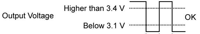 | 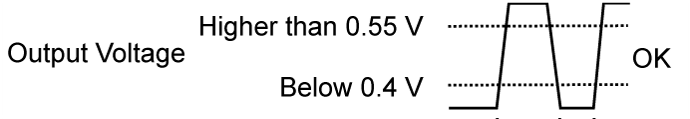 | - |
| 2 |  | | Air fuel ratio sensor Air fuel ratio sensor heater Air fuel ratio sensor circuit |
| 3 | | | Heated oxygen sensor Heated oxygen sensor heater Heated oxygen sensor circuit |
| 4 | | | Fuel injector assembly Fuel pressure Gas leakage from exhaust system (air fuel ratio extremely rich or lean) |
- HINT:
| 1.CHECK FOR ANY OTHER DTCS OUTPUT (IN ADDITION TO DTC P2A00 AND/OR P2A03) |
Connect the GTS to the DLC3.
Turn the ignition switch to ON.
Turn the GTS on.
Enter the following menus: Powertrain / Engine and ECT / Trouble Codes.
Read DTCs.
| Result | Proceed to |
| P2A00 and/or P2A03 | A |
| P2A00 and/or P2A03 and other DTCs | B |
- HINT:
- If any DTCs other than P2A00 or P2A03 are output, troubleshoot those DTCs first.
|
| ||||
| A | |
| 2.INSPECT AIR FUEL RATIO SENSOR (HEATER RESISTANCE) |
Inspect the air fuel ratio sensor ().
|
| ||||
| OK | |
| 3.CHECK HARNESS AND CONNECTOR (AIR FUEL RATIO SENSOR - ECM) |
Disconnect the air fuel ratio sensor connector.
Disconnect the ECM connector.
Measure the resistance according to the value(s) in the table below.
- Standard Resistance:
for LHD Tester Connection Condition Specified Condition C22-1 (HA1A) - C45-22 (HA1A) Always Below 1 Ω C23-1 (HA2A) - C45-20 (HA2A) Always Below 1 Ω C22-1 (HA1A) or C45-22 (HA1A) - Body ground Always 10 kΩ or higher C23-1 (HA2A) or C45-20 (HA2A) - Body ground Always 10 kΩ or higher for RHD Tester Connection Condition Specified Condition C22-1 (HA1A) - C46-22 (HA1A) Always Below 1 Ω C23-1 (HA2A) - C46-20 (HA2A) Always Below 1 Ω C22-1 (HA1A) or C46-22 (HA1A) - Body ground Always 10 kΩ or higher C23-1 (HA2A) or C46-20 (HA2A) - Body ground Always 10 kΩ or higher
Reconnect the air fuel ratio sensor connector.
Reconnect the ECM connector.
|
| ||||
| OK | |
| 4.PERFORM CONFIRMATION DRIVING PATTERN |
| NEXT | |
| 5.CHECK WHETHER DTC OUTPUT RECURS (DTC P2A00 AND/OR P2A03) |
Connect the GTS to the DLC3.
Turn the ignition switch to ON and turn the GTS on.
Enter the following menus: Powertrain / Engine and ECT / Trouble Codes / Pending.
Read DTCs.
| Result | Proceed to |
| P2A00 and/or P2A03 | A |
| No output | B |
|
| ||||
| A | |
| 6.REPLACE AIR FUEL RATIO SENSOR |
Replace the air fuel ratio sensor ().
| NEXT | |
| 7.PERFORM CONFIRMATION DRIVING PATTERN |
| NEXT | |
| 8.CHECK WHETHER DTC OUTPUT RECURS (DTC P2A00 AND/OR P2A03) |
Connect the GTS to the DLC3.
Turn the ignition switch to ON and turn the GTS on.
Enter the following menus: Powertrain / Engine and ECT / Trouble Codes / Pending.
Read DTCs.
| Result) | Proceed to |
| No output | A |
| P2A00 and/or P2A03 | B |
|
| ||||
| A | ||
| ||