Land Cruiser URJ200 URJ202 GRJ200 VDJ200 - 1GR-FE ENGINE CONTROL
CHECK HARNESS AND CONNECTOR (EMISSION CONTROL VALVE SET - ECM)
CHECK TERMINAL VOLTAGE (VC OF EMISSION CONTROL VALVE SET)
REPLACE EMISSION CONTROL VALVE SET
CHECK WHETHER DTC OUTPUT RECURS
DTC P2431 Secondary Air Injection System Air Flow / Pressure Sensor Circuit Range / Performance Bank1
DTC P2432 Secondary Air Injection System Air Flow / Pressure Sensor Circuit Low Bank1
DTC P2433 Secondary Air Injection System Air Flow / Pressure Sensor Circuit High Bank1
DTC P2436 Secondary Air Injection System Air Flow / Pressure Sensor Circuit Range / Performance Bank 2
DTC P2437 Secondary Air Injection System Air Flow / Pressure Sensor Circuit Low Bank 2
DTC P2438 Secondary Air Injection System Air Flow / Pressure Sensor Circuit High Bank 2
DESCRIPTION
Refer to DTC P0412 ().
Refer to DTC P0416 ().
| DTC No. | DTC Detection Condition | Trouble Area |
| P2431 P2436 | Pressure sensor indicates a value below 45.6 kPa (342 mmHg), or higher than 135 kPa (1013 mmHg) (2 trip detection logic). | Emission control valve set Open or short in pressure sensor circuit ECM |
| P2432 P2437 | While the engine is running, the voltage output of the pressure sensor is below 0.5 V (1 trip detection logic). | Emission control valve set Open or short in pressure sensor circuit ECM |
| P2433 P2438 | While the engine is running, the voltage output of the pressure sensor is higher than 4.5 V (1 trip detection logic). | Emission control valve set Open or short in pressure sensor circuit ECM |
MONITOR DESCRIPTION

The ECM monitors the pressure in the secondary air passage using the pressure sensor located on the emission control valve set in the secondary air injection system. Using this pressure value, the ECM determines whether the secondary air injection system is malfunctioning or not.
If there is a defect in the sensor or the sensor circuit, the voltage level deviates from the normal operating range. The ECM interprets this deviation as a malfunction in the pressure sensor or circuit and stores a DTC.
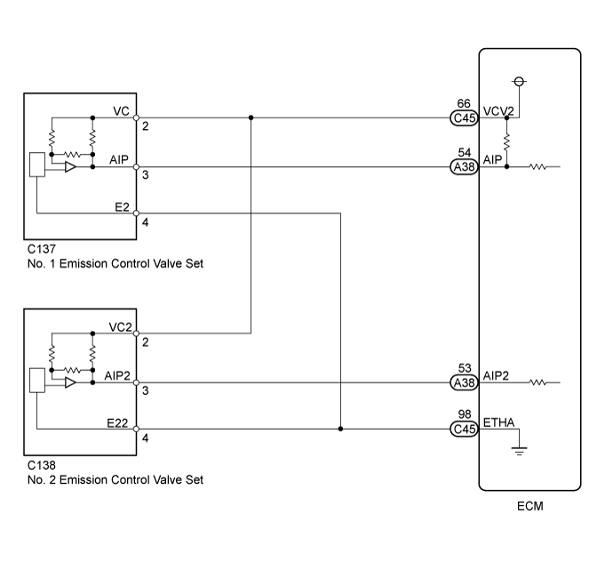
WIRING DIAGRAM
INSPECTION PROCEDURE
- HINT:
*: The No. 1 cylinder is the cylinder which is farthest from the transmission.
| 1.CHECK HARNESS AND CONNECTOR (EMISSION CONTROL VALVE SET - ECM) |
Disconnect the emission control valve set connector.
Disconnect the ECM connectors.
Measure the resistance according to the value(s) in the table below.
- Standard Resistance:
Tester Connection Condition Specified Condition C137-3 (AIP) - A38-54 (AIP) Always Below 1 Ω C137-2 (VC) - C45-66 (VCV2) Always Below 1 Ω C137-4 (E2) - C45-98 (ETHA) Always Below 1 Ω C138-3 (AIP2) - A38-53 (AIP2) Always Below 1 Ω C138-2 (VC2) - C45-66 (VCV2) Always Below 1 Ω C138-4 (E22) - C45-98 (ETHA) Always Below 1 Ω C137-3 (AIP) or A38-54 (AIP) - Body ground Always 10 kΩ or higher C137-2 (VC) or C45-66 (VCV2) - Body ground Always 10 kΩ or higher C138-3 (AIP2) or A38-53 (AIP2) - Body ground Always 10 kΩ or higher C138-2 (VC2) or C45-66 (VCV2) - Body ground Always 10 kΩ or higher
|
| ||||
| OK | |
| 2.CHECK TERMINAL VOLTAGE (VC OF EMISSION CONTROL VALVE SET) |

Disconnect the emission control valve set connector.
Turn the ignition switch to ON.
Measure the voltage according to the value(s) in the table below.
- Standard Voltage:
Tester Connection Switch Condition Specified Condition C137-2 (VC) - C137-4 (E2) Ignition switch ON 4.5 to 5.5 V C138-2 (VC2) - C138-4 (E22) Ignition switch ON 4.5 to 5.5 V
| *A | for Bank 1 |
| *B | for Bank 2 |
| *a | Front view of wire harness connector (to Emission Control Valve Set) |
|
| ||||
| OK | |
| 3.REPLACE EMISSION CONTROL VALVE SET |
Replace the emission control valve set.
- HINT:
| NEXT | |
| 4.CHECK WHETHER DTC OUTPUT RECURS |
Start the engine and warm it up.
Turn the ignition switch off.
Connect the GTS to the DLC3.
Turn the ignition switch to ON.
Turn the GTS on.
Clear the DTCs (if stored) ().
Enter the following menus: Powertrain / Engine and ECT / Utility / Secondary Air Injection Check / Automatic Mode.
Start the engine after the GTS initialization is finished.
Perform the System Check operation by pressing ENTER (Next).
Perform the following to confirm the secondary air injection system pending codes: Press the Exit button.
Check for pending DTCs.
- OK:
- No pending DTC is output.
Turn the ignition switch off.
- NOTICE:
|
| ||||
| OK | ||
| ||