INSTALL REAR TELEVISION CAMERA ASSEMBLY (w/ Rear View Monitor System)
INSTALL BACK DOOR NO. 2 OUTSIDE GARNISH (w/ Rear View Monitor System)
Tail Gate -- Reassembly |
- HINT:
- A bolt without a torque specification is shown in the standard bolt chart (HILUX_TGN26 RM00000118R007X.html).
| 1. INSTALL TAIL GATE HINGE ASSEMBLY LH |
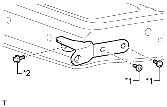 |
Install the tail gate hinge with the bolt.
- Torque:
- 18 N*m{184 kgf*cm, 13 ft.*lbf}
Using a T40 "TORX" socket wrench, install the 2 "TORX" bolts.
- Torque:
- 28 N*m{286 kgf*cm, 21 ft.*lbf}
Text in Illustration *1 "TORX" Bolt *2 Bolt
| 2. INSTALL TAIL GATE HINGE ASSEMBLY RH |
- HINT:
- Use the same procedure described for the LH side.
| 3. INSTALL TAIL GATE STAY STOPPER (for A Deck) |
- HINT:
- Use the same procedure for both tail gate stay stoppers.
Install the tail gate stay stopper with the bolt.
| 4. INSTALL TAIL GATE LOCK ASSEMBLY LH (for A Deck) |
Install the tail gate lock with the 2 bolts.
- Torque:
- 13 N*m{127 kgf*cm, 9 ft.*lbf}
| 5. INSTALL TAIL GATE LOCK ASSEMBLY RH (for A Deck) |
- HINT:
- Use the same procedure described for the LH side.
| 6. INSTALL TAIL GATE HANDLE ASSEMBLY (for A Deck) |
Install the tail gate handle with the 2 bolts.
- Torque:
- 5.0 N*m{51 kgf*cm, 44 in.*lbf}
| 7. INSTALL TAIL GATE LOCK CONTROL LINK LH (for A Deck) |
Install the tail gate lock control link.
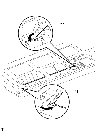 |
Rotate the control link snaps in the directions indicated by the arrows in the illustration and attach the control link snaps to the tail gate lock control link.
Text in Illustration *1 Snap
| 8. INSTALL TAIL GATE LOCK CONTROL LINK RH (for A Deck) |
- HINT:
- Use the same procedure described for the LH side.
| 9. INSTALL REAR BODY TAIL GATE LATCH ASSEMBLY (for J Deck) |
- HINT:
- Use the same procedure for both rear body tail gate latches.
Install the rear body tail gate latch with the 2 bolts.
- Torque:
- 5.0 N*m{51 kgf*cm, 44 in.*lbf}
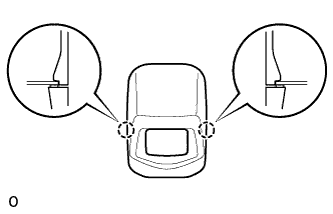
| 10. INSTALL REAR TELEVISION CAMERA ASSEMBLY (w/ Rear View Monitor System) |
Attach the 2 guides as shown in the illustration.
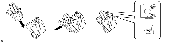
- HINT:
- Make sure that each guide is attached to its corresponding rail.
Attach the 2 claws to install the rear television camera assembly.
- NOTICE:
- Visually check that the guides and claws are attached to the back door No. 2 outside garnish.
| 11. INSTALL BACK DOOR NO. 2 OUTSIDE GARNISH (w/ Rear View Monitor System) |
Attach the claw and 2 guides as shown in the illustration.
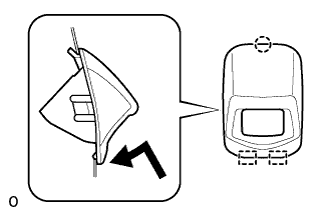 |
Attach the 2 claws to install the back door No. 2 outside garnish.
 |
Connect the connector.
- NOTICE:
- Make sure that the wire harness is between the tail gate inner panel and tail gate lock control link.
Text in Illustration *1 Tail Gate Lock Control Link
 |
| 12. INSTALL CENTER STOP LIGHT ASSEMBLY (w/ Center Stop Light) |
Attach the 4 claws to install the center stop light assembly.
Connect the connector.
| 13. INSTALL TAIL GATE SERVICE HOLE COVER |
for A Deck:
Install the tail gate service hole cover with the 10 screws.
for J Deck:
Install the tail gate service hole cover with the 8 screws.