Power Window Control System (W/ Jam Protection Function) Rear Power Window Lh Manual Function Does Not Operate With Rear Power Window Switch Lh
DESCRIPTION
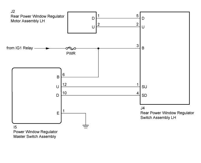
WIRING DIAGRAM
INSPECTION PROCEDURE
CHECK HARNESS AND CONNECTOR (REAR POWER WINDOW REGULATOR SWITCH ASSEMBLY LH - BATTERY)
INSPECT REAR POWER WINDOW REGULATOR SWITCH ASSEMBLY LH
CHECK HARNESS AND CONNECTOR (REAR POWER WINDOW REGULATOR SWITCH ASSEMBLY LH - REAR POWER WINDOW REGULATOR MOTOR ASSEMBLY LH)
INSPECT REAR POWER WINDOW REGULATOR MOTOR ASSEMBLY LH
CHECK HARNESS AND CONNECTOR (POWER WINDOW REGULATOR MASTER SWITCH ASSEMBLY - REAR POWER WINDOW REGULATOR SWITCH ASSEMBLY LH)
POWER WINDOW CONTROL SYSTEM (w/ Jam Protection Function) - Rear Power Window LH Manual Function does not Operate with Rear Power Window Switch LH |
DESCRIPTION
If the rear LH side manual up/down function does not operate, a malfunction may be present in the rear power window regulator motor assembly LH, rear power window regulator switch assembly LH, power window regulator master switch assembly or wire harness.
WIRING DIAGRAM
INSPECTION PROCEDURE
- NOTICE:
- Inspect the fuses for circuits related to this system before performing the following inspection procedure.
| 1.CHECK HARNESS AND CONNECTOR (REAR POWER WINDOW REGULATOR SWITCH ASSEMBLY LH - BATTERY) |
Disconnect the J4 rear power window regulator switch assembly LH connector.
Measure the voltage according to the value(s) in the table below.
- Standard Voltage:
Tester Connection
| Switch Condition
| Specified Condition
|
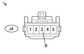
J4-3 (B) - Body ground
| Ignition switch ON
| 11 to 14 V
|
Ignition switch off
| Below 1 V
|
Text in Illustration*a
| Front view of wire harness connector
(to Rear Power Window Regulator Switch Assembly LH)
|
| | REPAIR OR REPLACE HARNESS OR CONNECTOR |
|
|
| 2.INSPECT REAR POWER WINDOW REGULATOR SWITCH ASSEMBLY LH |
Remove the rear power window regulator switch assembly LH (HILUX_TGN26 RM000002STU059X.html).
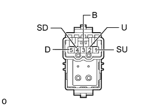
Measure the resistance according to the value(s) in the table below.
- Standard Resistance:
Tester Connection
| Switch Condition
| Specified Condition
|
5 (D) - 4 (SD)
| UP
| Below 1 Ω
|
2 (U) - 3 (B)
|
5 (D) - 4 (SD)
| OFF
| Below 1 Ω
|
2 (U) - 1 (SU)
|
5 (D) - 3 (B)
| DOWN
| Below 1 Ω
|
2 (U) - 1 (SU)
|
| 3.CHECK HARNESS AND CONNECTOR (REAR POWER WINDOW REGULATOR SWITCH ASSEMBLY LH - REAR POWER WINDOW REGULATOR MOTOR ASSEMBLY LH) |
Disconnect the J4 rear power window regulator switch assembly LH connector.
Disconnect the J2 rear power window regulator motor assembly LH connector.
Measure the resistance according to the value(s) in the table below.
- Standard Resistance:
Tester Connection
| Condition
| Specified Condition
|
J4-5 (D) - J2-1 (D)
| Always
| Below 1 Ω
|
J4-2 (U) - J2-2 (U)
| Always
| Below 1 Ω
|
J4-5 (D) or J2-1 (D) - Body ground
| Always
| 10 kΩ or higher
|
J4-2 (U) or J2-2 (U) - Body ground
| Always
| 10 kΩ or higher
|
| | REPAIR OR REPLACE HARNESS OR CONNECTOR |
|
|
| 4.INSPECT REAR POWER WINDOW REGULATOR MOTOR ASSEMBLY LH |
Remove the rear power window regulator motor assembly LH (HILUX_TGN26 RM000002M8102WX.html).
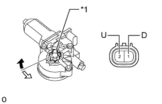
Apply battery voltage to connector terminals 1 (D) and 2 (U).
Check that the motor gear rotates smoothly as follows.
- OK:
Measurement Condition
| Specified Condition
|
Battery positive (+) → 1 (D)
Battery negative (-) → 2 (U)
| Motor gear rotates counterclockwise
|
Battery positive (+) → 2 (U)
Battery negative (-) → 1 (D)
| Motor gear rotates clockwise
|
Text in Illustration*1
| Motor Gear
|

| Clockwise
|

| Counterclockwise
|
| 5.CHECK HARNESS AND CONNECTOR (POWER WINDOW REGULATOR MASTER SWITCH ASSEMBLY - REAR POWER WINDOW REGULATOR SWITCH ASSEMBLY LH) |
Disconnect the I5 power window regulator master switch assembly connector.
Disconnect the J4 rear power window regulator switch assembly LH connector.
Measure the resistance according to the value(s) in the table below.
- Standard Resistance:
Tester Connection
| Condition
| Specified Condition
|
I5-12 (U) - J4-1 (SU)
| Always
| Below 1 Ω
|
I5-10 (D) - J4-4 (SD)
| Always
| Below 1 Ω
|
I5-12 (U) or J4-1 (SU) - Body ground
| Always
| 10 kΩ or higher
|
I5-10 (D) or J4-4 (SD) - Body ground
| Always
| 10 kΩ or higher
|
| | REPAIR OR REPLACE HARNESS OR CONNECTOR |
|
|