INSTALL HEATER CONTROL CABLE SUB-ASSEMBLY (for Manual Air Conditioning System)
INSTALL AIR MIX DAMPER CONTROL CABLE SUB-ASSEMBLY (for Manual Air Conditioning System)
INSTALL MODE DAMPER SERVO SUB-ASSEMBLY (for Automatic Air Conditioning System)
INSTALL AIR MIX DAMPER SERVO SUB-ASSEMBLY (for Automatic Air Conditioning System)
INSTALL AIR CONDITIONING AMPLIFIER ASSEMBLY (for Manual Air Conditioning System)
Air Conditioning Unit -- Reassembly |
| 1. INSTALL NO. 1 COOLER THERMISTOR |
 |
- NOTICE:
- If reusing the evaporator, do not insert the sensor at a location where the sensor was previously inserted. Insert the sensor within range C shown in the illustration.
Insert the No. 1 cooler thermistor (front evaporator temperature sensor) as shown in the illustration to install it.
| 2. INSTALL COOLER EXPANSION VALVE |
Sufficiently apply compressor oil to 2 new O-rings and the fitting surface of the hose joint.
- Compressor oil:
- ND-OIL 8 or equivalent
Install the 2 O-rings to the cooler evaporator.
Using a 4 mm socket hexagon wrench, install the cooler expansion valve with the 2 hexagon bolts.
- Torque:
- 3.5 N*m{35 kgf*cm, 30 in.*lbf}
| 3. INSTALL NO. 1 COOLER EVAPORATOR SUB-ASSEMBLY |
Attach the clamp to install the No. 1 cooler evaporator sub-assembly.
Attach the 3 claws to install the lower heater case.
Install the 4 screws.
| 4. INSTALL HEATER RADIATOR UNIT SUB-ASSEMBLY |
Attach the evaporator case to the blower case.
Install the heater radiator unit sub-assembly with the screw.
| 5. INSTALL BLOWER ASSEMBLY |
Install the blower assembly with the 3 screws.
| 6. INSTALL HEATER CONTROL CABLE SUB-ASSEMBLY (for Manual Air Conditioning System) |
Attach the 3 claws to install the heater control cable sub-assembly.
| 7. INSTALL AIR MIX DAMPER CONTROL CABLE SUB-ASSEMBLY (for Manual Air Conditioning System) |
Attach the 3 claws to install the air mix damper control cable sub-assembly.
| 8. INSTALL MODE DAMPER SERVO SUB-ASSEMBLY (for Automatic Air Conditioning System) |
Install the mode damper servo sub-assembly with the 3 screws.
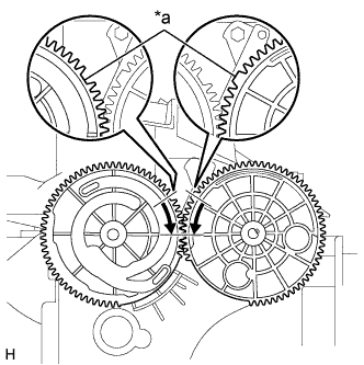
Set the mode damper servo sub-assembly so that the tooth of the gear engages with the cutout part as shown in the illustration to install the lever.
Text in Illustration *a Cut Part
 |
Attach the claw.
| 9. INSTALL AIR MIX DAMPER SERVO SUB-ASSEMBLY (for Automatic Air Conditioning System) |
Install the air mix damper servo sub-assembly with the 3 screws.
| 10. INSTALL AIR CONDITIONING AMPLIFIER ASSEMBLY (for Manual Air Conditioning System) |
Install the air conditioning amplifier assembly with the screw.
Connect the connector.
Attach the clamp.