Air Conditioning System (For Automatic Air Conditioning System) System Description
GENERAL
MODE POSITION AND DAMPER OPERATION
AIR OUTLETS AND AIR FLOW VOLUME
Air Conditioning System (For Automatic Air Conditioning System) -- System Description |
The air conditioning system has the following features:
- The air conditioning amplifier assembly is equipped with a self-diagnosis function. If there is a malfunction in the system, it stores DTCs in its memory and the air conditioning switch indicator blinks.
- The air conditioning amplifier assembly receives the vehicle speed signal from the combination meter.
- The recirculation damper servo sub-assembly, air mix damper servo sub-assembly and mode damper servo sub-assembly rely on their built-in pulse sensors to detect their respective motor rotation angles.
- The servo motor rotation angle zero point calibration is necessary in the following situations: 1) the servo motor deviates from the calibrated position, 2) the air conditioning amplifier assembly backup power source is cut, or 3) the air conditioning amplifier assembly or servo motor is replaced.
For 1, when the ignition switch is turned off, zero point calibration of the air conditioning amplifier assembly is automatically performed. For 2 and 3, when the backup power source returns and the ignition switch is turned to ON, zero point calibration of the air conditioning amplifier assembly is automatically performed.
While zero point calibration is being performed, the following occurs: 1) the DEF indicator blinks at 1 second intervals, but the air conditioning amplifier assembly other outputs are disabled; and 2) the air conditioning system switches do not function.
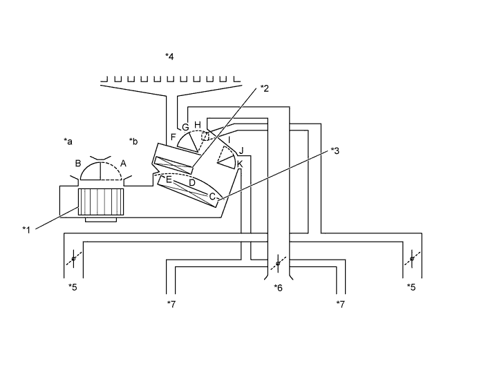
| MODE POSITION AND DAMPER OPERATION |
Text in Illustration*1
| Blower with Fan Motor Sub-assembly
| *2
| Heater Radiator Unit Sub-assembly
|
*3
| No. 1 Cooler Evaporator Sub-assembly
| *4
| Front Defroster
|
*5
| Side Register
| *6
| Center Register
|
*7
| Front Footwell Register Duct
| -
| -
|
*a
| Fresh Air
| *b
| Recirculated Air
|
- HINT:
- This Illustration is damper operation image. The number and location of the dampers is different to the actual unit.
Control Damper
| Operation Position
| Damper Position
| Operation
|
Air Inlet Control Damper
| FRESH
| A
| Brings in fresh air.
|
RECIRC
| B
| Recirculates internal air.
|
Air Mix Control Damper
| MAX COLD - MAX HOT
| C, D, E
| Varies mixture ratio of cool air and warm air in order to regulate temperature continuously from HOT to COLD.
|
Mode Damper
| FACE
| 
| F, K
| Air blows out of the center registers and side register.
|
BI-LEVEL
| 
| F, J
| Air blows our of the center registers, side registers and foot well register ducts.
|
FOOT
| 
| G, I
| Air blows out of the foot well register ducts and side register. In addition, air blows out slightly from the front defroster.
|
FOOT/DEF
| 
| H, I
| Defrosts the windshield through the front defroster and side register, while air is also blown out from the foot well register ducts.
|
DEF
| 
| H, K
| Defrosts the windshield through the front defroster and side register.
|
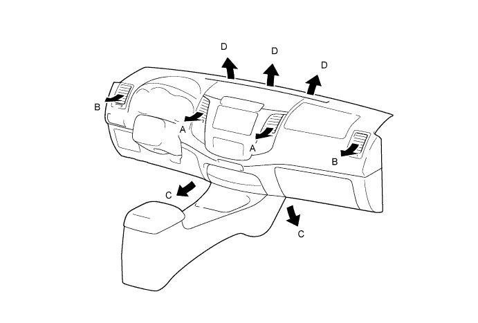
| AIR OUTLETS AND AIR FLOW VOLUME |
Indication
| Mode
| A
| B
| C
| D
|
Center
| Side
| Footwell
| Defroster
|
| FACE
| 
|
| -
| -
|
| BI-LEVEL
| 
|
| 
| -
|
| FOOT
| -
|
|
|
|
| FOOT / DEF
| -
|
|
|
|
| DEF
| -
|
| -
|
|
- HINT:
- The circle size (○) is proportional to the amount of air flow.