Airbag System Srs Warning Light Remains On
DESCRIPTION
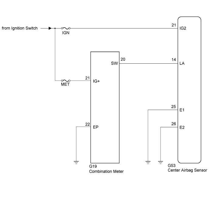
WIRING DIAGRAM
INSPECTION PROCEDURE
INSPECT BATTERY
CHECK CONNECTION OF CONNECTOR
CHECK HARNESS AND CONNECTOR (SOURCE VOLTAGE OF CENTER AIRBAG
SENSOR)
CHECK HARNESS AND CONNECTOR (SOURCE VOLTAGE OF COMBINATION METER)
CHECK HARNESS AND CONNECTOR (CENTER AIRBAG SENSOR - COMBINATION METER)
CHECK SRS WARNING LIGHT (OPERATION)
CHECK CENTER AIRBAG SENSOR ASSEMBLY
REPLACE CENTER AIRBAG SENSOR ASSEMBLY
AIRBAG SYSTEM - SRS Warning Light Remains ON |
DESCRIPTION
The SRS warning light is located on the combination meter. When the ignition switch is turned from off to ON, the SRS warning light illuminates. If the SRS is normal, the SRS warning light turns off automatically after approximately 6 seconds. If there is a malfunction in the SRS, the SRS warning light remains illuminated even after approximately 6 seconds have passed. When terminals TC and CG of the DLC3 are connected, the DTCs are communicated through SRS warning light blinking patterns.
WIRING DIAGRAM
INSPECTION PROCEDURE
- NOTICE:
- After turning the ignition switch off, waiting time may be required before disconnecting the cable from the battery terminal. Therefore, make sure to read the disconnecting the cable from the battery terminal notice before proceeding with work (HILUX_TGN26 RM000004QR1006X.html).
- When disconnecting the cable from the negative (-) battery terminal while performing repairs, some systems need to be initialized after the cable is reconnected (HILUX_TGN26 RM000004QR3008X.html).
- Inspect the fuses for circuits related to this system before performing the following inspection procedure.
Measure the voltage of the battery.
- Standard voltage:
- 11 to 14 V
| | RECHARGE OR REPLACE BATTERY |
|
|
| 2.CHECK CONNECTION OF CONNECTOR |
Turn the ignition switch off.
Disconnect the cable from the negative (-) battery terminal, and wait for at least 90 seconds.
Check that the connectors are properly connected to the center airbag sensor and combination meter.
- OK:
- The connectors are properly connected.
| | CONNECT CONNECTORS PROPERLY |
|
|
| 3.CHECK HARNESS AND CONNECTOR (SOURCE VOLTAGE OF CENTER AIRBAG
SENSOR) |
Disconnect the connector from the center airbag sensor.
Connect the cable to the negative (-) battery terminal, and wait for at least 2 seconds.
Turn the ignition switch to ON.
Operate all the components of the electrical system (defogger, wipers, headlights, heater blower, etc.).
Measure the voltage according to the value(s) in the table below.
- Standard Voltage:
Tester Connection
| Switch Condition
| Specified Condition
|
G53-21 (IG2) - Body ground
| Ignition switch ON
| 11 to 14 V
|
Turn the ignition switch off.
Disconnect the cable from the negative (-) battery terminal, and wait for at least 90 seconds.
Measure the resistance according to the value(s) in the table below.
- Standard Resistance:
Tester Connection
| Condition
| Specified Condition
|
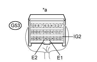
G53-25 (E1) - Body ground
| Always
| Below 1 Ω
|
G53-26 (E2) - Body ground
| Always
| Below 1 Ω
|
Text in Illustration*a
| Rear view of wire harness connector
(to Center Airbag Sensor)
|
| | REPLACE HARNESS AND CONNECTOR |
|
|
| 4.CHECK HARNESS AND CONNECTOR (SOURCE VOLTAGE OF COMBINATION METER) |
Disconnect the G19 connector from the combination meter.
Connect the cable to the negative (-) battery terminal, and wait for at least 2 seconds.
Turn the ignition switch to ON.
Measure the voltage according to the value(s) in the table below.
- Standard Voltage:
Tester Connection
| Switch Condition
| Specified Condition
|
G19-21 (IG+) - Body ground
| Ignition switch ON
| 11 to 14 V
|
Turn the ignition switch off.
Disconnect the cable from the negative (-) battery terminal, and wait for at least 90 seconds.
Measure the resistance according to the value(s) in the table below.
- Standard Resistance:
Tester Connection
| Condition
| Specified Condition
|
G19-22 (EP) - Body ground
| Always
| Below 1 Ω
|
Text in Illustration*a
| Front view of wire harness connector
(to Combination Meter)
|
| | REPAIR OR REPLACE HARNESS OR CONNECTOR |
|
|
| 5.CHECK HARNESS AND CONNECTOR (CENTER AIRBAG SENSOR - COMBINATION METER) |
Measure the resistance according to the value(s) in the table below.
- Standard Resistance:
Tester Connection
| Condition
| Specified Condition
|
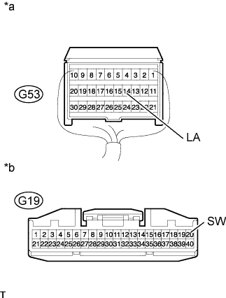
G53-14 (LA) - G19-20 (SW)
| Always
| Below 1 Ω
|
G53-14 (LA) - Body ground
| Always
| 10 kΩ or higher
|
Text in Illustration*a
| Rear view of wire harness connector
(to Center Airbag Sensor)
|
*b
| Front view of wire harness connector
(to Combination Meter)
|
| | REPLACE HARNESS AND CONNECTOR |
|
|
| 6.CHECK SRS WARNING LIGHT (OPERATION) |
Connect the connector to the combination meter.
Connect the cable to the negative (-) battery terminal, and wait for at least 2 second.
Turn the ignition switch to ON.
Check the SRS warning light condition.
- NOTICE:
- Make sure that nobody is in the vehicle.
- OK:
- After the primary check period, the SRS warning light goes off for approximately 10 seconds and then remains on.
- HINT:
- The primary check period is approximately 6 seconds after the ignition switch is turned to ON.
| 7.CHECK CENTER AIRBAG SENSOR ASSEMBLY |
Turn the ignition switch to ON.
Measure the voltage according to the value(s) in the table below.
- Standard Voltage:
Tester Connection
| Switch Condition
| Specified Condition
|
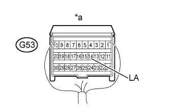
G53-14 (LA) - Body ground
| Ignition switch ON
| 11 to 14 V
|
Text in Illustration*a
| Rear view of wire harness connector
(to Center Airbag Sensor)
|
| 8.REPLACE CENTER AIRBAG SENSOR ASSEMBLY |
Turn the ignition switch off.
Disconnect the cable from the negative (-) battery terminal, and wait for at least 90 seconds.
Replace the center airbag sensor (HILUX_TGN26 RM0000010IE012X.html).
Check the SRS warning light condition.
- OK:
- SRS warning light illuminates normally.
| OK |
|
|
|
| END (CENTER AIRBAG SENSOR IS DEFECTIVE) |
|