Meter / Gauge System -- Terminals Of Ecu |
| CHECK COMBINATION METER ASSEMBLY |
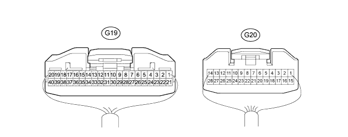
Disconnect the G19 and G20 combination meter assembly connectors.
Measure the voltage and resistance according to the value(s) in the table below.
*1: w/ Light Control RheostatTerminal No. (Symbol) Wiring Color Terminal Description Condition Specified Condition G19-1 (B) - Body ground R - Body ground Battery Always 11 to 14 V G19-9 (TR) - Body ground*1 W-B - Body ground Rheostat signal Rheostat knob fully turned to left 666.9 to 737.1 Ω G19-9 (TR) - Body ground*1 W-B - Body ground Rheostat signal Rheostat knob fully turned to right Below 1 Ω G19-9 (TR) - Body ground*5 W-B - Body ground Ground Always Below 1 Ω G19-19 (ABOF) - Body ground*2 W-B - Body ground Ground Always Below 1 Ω G19-21 (IG+) - Body ground B-O - Body ground IG2 signal Ignition switch ON 11 to 14 V G19-21 (IG+) - Body ground B-O - Body ground IG2 signal Ignition switch off Below 1 V G19-22 (EP) - Body ground Y - Body ground Ground Always Below 1 Ω G19-26 (PKBI) - Body ground*3 W-B - Body ground Ground Always Below 1 Ω G19-38 (LP) - Body ground*4 R-G - Body ground Ground Always Below 1 Ω
*2: w/o Airbag System
*3: w/o VSC
*4: w/o Anti-lock Brake System
*5: w/o Light Control RheostatReconnect the G19 and G20 combination meter assembly connectors.
Measure the voltage according to the value(s) in the table below.
*1: for Automatic TransmissionTerminal No. (Symbol) Wiring Color Terminal Description Condition Specified Condition G19-2 (ES) - G19-3 (L) BR - BR-Y Fuel level signal Ignition switch ON, fuel level F Below 1 V G19-2 (ES) - G19-3 (L) BR - BR-Y Fuel level signal Ignition switch ON, fuel level E 4 to 7 V G19-5 (SI) - Body ground P-L - Body ground Vehicle speed signal (input) Driving at approx. 20 km/h (12 mph) Pulse generation (See waveform 1) G19-6 (+S) - Body ground V-R - Body ground Vehicle speed signal (output) Driving at approx. 20 km/h (12 mph) Pulse generation (See waveform 1) G19-7 (S) - Body ground B-W - Body ground Tachometer signal Engine idling Pulse generation (See waveform 2) G19-8 (ILL+) - Body ground G - Body ground Light control switch signal Light control switch off Below 1 V G19-8 (ILL+) - Body ground G - Body ground Light control switch signal Light control switch TAIL or HEAD 11 to 14 V G19-10 (KSW) - Body ground G-Y - Body ground Unlock warning switch signal No key in ignition key cylinder Below 1 V G19-10 (KSW) - Body ground G-Y - Body ground Unlock warning switch signal Ignition switch off, key in ignition key cylinder 11 to 14 V G19-11 (BKL) - Body ground R-Y - Body ground Driver side seat belt warning signal Ignition switch ON, driver side seat belt unfastened Below 1 V G19-11 (BKL) - Body ground R-Y - Body ground Driver side seat belt warning signal Ignition switch ON, driver side seat belt fastened 11 to 14 V G19-12 (P) - Body ground*1 G-B - Body ground Automatic transmission shift position signal (P) Ignition switch ON, automatic transmission P indicator light off Below 1 V G19-12 (P) - Body ground*1 G-B - Body ground Automatic transmission shift position signal (P) Ignition switch ON, automatic transmission P indicator light on 11 to 14 V G19-13 (L) - Body ground*1, *2 W-G - Body ground A/T P warning light signal Ignition switch ON, shift lever in P, A/T P warning light on Below 1 V G19-13 (L) - Body ground*1, *2 W-G - Body ground A/T P warning light signal Ignition switch ON, shift lever in P, A/T P warning light off 11 to 14 V G19-14 (FFTR) - Body ground*3 W-G - Body ground FUEL FILTER warning light signal Ignition switch ON, FUEL FILTER warning light on Below 1 V G19-14 (FFTR) - Body ground*3 W-G - Body ground FUEL FILTER warning light signal Ignition switch ON, FUEL FILTER warning light off 11 to 14 V G19-15 (CTYD) - Body ground R-B - Body ground Driver side door signal (output) Driver side door closed 11 to 14 V G19-15 (CTYD) - Body ground R-B - Body ground Driver side door signal (output) Driver side door open Below 1 V G19-16 (DCTY) - Body ground R-B - Body ground Driver side door signal (input) Driver side door closed 11 to 14 V G19-16 (DCTY) - Body ground R-B - Body ground Driver side door signal (input) Driver side door open Below 1 V G19-17 (DOOR) - Body ground R-L - Body ground Door signal Doors closed (Disregarding driver side door) 11 to 14 V G19-17 (DOOR) - Body ground R-L - Body ground Door signal Doors open (Disregarding driver side door) Below 1 V G19-18 (OILW) - Body ground*1, *2 P - Body ground A/T OIL TEMP warning light signal Ignition switch ON, A/T OIL TEMP warning light on Below 1 V G19-18 (OILW) - Body ground*1, *2 P - Body ground A/T OIL TEMP warning light signal Ignition switch ON, A/T OIL TEMP warning light off 11 to 14 V G19-20 (SW) - Body ground*4 B-Y - Body ground SRS warning light signal Ignition switch ON, SRS warning light off Pulse generation (See waveform 3) G19-20 (SW) - Body ground*4 B-Y - Body ground SRS warning light signal Ignition switch ON, SRS warning light on Pulse generation (See waveform 4) G19-23 (S) - Body ground*3 L-R - Body ground FUEL FILTER warning light signal Ignition switch ON, FUEL FILTER warning light on Below 1 V G19-23 (S) - Body ground*3 L-R - Body ground FUEL FILTER warning light signal Ignition switch ON, FUEL FILTER warning light off 11 to 14 V G19-24 (B) - Body ground G-B - Body ground Turn signal indicator LH signal Ignition switch ON, turn signal indicator LH light off Below 1 V G19-24 (B) - Body ground G-B - Body ground Turn signal indicator LH signal Ignition switch ON, turn signal indicator LH light on 11 to 14 V G19-25 (B) - Body ground G-Y - Body ground Turn signal indicator RH signal Ignition switch ON, turn signal indicator RH light off Below 1 V G19-25 (B) - Body ground G-Y - Body ground Turn signal indicator RH signal Ignition switch ON, turn signal indicator RH light on 11 to 14 V G19-26 (PKBI) - Body ground*5 LG - Body ground BRAKE indicator light signal Ignition switch ON, BRAKE indicator light off 11 to 14 V G19-26 (PKBI) - Body ground*5 LG - Body ground BRAKE indicator light signal Ignition switch ON, BRAKE indicator light on Below 1 V G19-27 (ST) - Body ground*10 B-Y - Body ground*1 Starter signal Shift lever in P*1 or N, ignition switch off Below 1 V L-Y - Body ground*11 G19-27 (ST) - Body ground*10 B-Y - Body ground*1 Starter signal Shift lever in P*1 or N, ignition switch START 11 to 14 V L-Y - Body ground*11 G19-29 (FLVL) - Body ground*10 W-G - Body ground Main fuel tank residual fuel amount Ignition switch ON, residual quantity of main fuel is 7.4L Pulse generation (See waveform 5) G19-29 (FLVL) - Body ground*10 W-G - Body ground Main fuel tank residual fuel amount Ignition switch ON, residual quantity of main fuel is 71.2L Pulse generation (See waveform 6) G19-31 (MS5) - Body ground R-B - Body ground IG signal (for Speedometer sensor) Ignition switch ON 11 to 14 V G19-31 (MS5) - Body ground R-B - Body ground IG signal (for Speedometer sensor) Ignition switch off Below 1 V G19-35 (S) - Body ground LG-B - Body ground OIL PRESSURE warning light signal Ignition switch ON, OIL PRESSURE warning light off 11 to 14 V G19-35 (S) - Body ground LG-B - Body ground OIL PRESSURE warning light signal Ignition switch ON, OIL PRESSURE warning light on Below 1 V G19-36 (SW) - Body ground LG - Body ground BRAKE warning light signal Ignition switch ON, BRAKE warning light off 11 to 14 V G19-36 (SW) - Body ground LG - Body ground BRAKE warning light signal Ignition switch ON, BRAKE warning light on Below 1 V G19-37 (CHG-) - Body ground GR - Body ground CHARGE warning light signal Ignition switch ON, CHARGE warning light off 11 to 14 V G19-37 (CHG-) - Body ground GR - Body ground CHARGE warning light signal Ignition switch ON, CHARGE warning light on Below 1 V G19-38 (LP) - Body ground*8 R-G - Body ground ABS warning light signal Ignition switch ON, ABS warning light off 11 to 14 V G19-38 (LP) - Body ground*8 R-G - Body ground ABS warning light signal Ignition switch ON, ABS warning light on Below 1 V G19-39 (CHK) - Body ground R-B - Body ground MIL signal Ignition switch ON, MIL off 11 to 14 V G19-39 (CHK) - Body ground R-B - Body ground MIL signal Ignition switch ON,
MIL onBelow 1 V G19-40 (GLW-) - Body ground*3 Y-R - Body ground GLOW indicator light signal Ignition switch ON, GLOW indicator light off 11 to 14 V G19-40 (GLW-) - Body ground*3 Y-R - Body ground GLOW indicator light signal Ignition switch ON, GLOW indicator light on Below 1 V G20-2 (2) - Body ground*1 G-R - Body ground Automatic transmission shift position signal (L) Ignition switch ON, automatic transmission L indicator light on 11 to 14 V G20-2 (2) - Body ground*1 G-R - Body ground Automatic transmission shift position signal (L) Ignition switch ON, automatic transmission L indicator light off Below 1 V G20-3 (3) - Body ground*1 L - Body ground Automatic transmission shift position signal (2) Ignition switch ON, automatic transmission 2 indicator light on 11 to 14 V G20-3 (3) - Body ground*1 L - Body ground Automatic transmission shift position signal (2) Ignition switch ON, automatic transmission 2 indicator light off Below 1 V G20-4 (4) - Body ground*1 G-O - Body ground Automatic transmission shift position signal (3) Ignition switch ON, automatic transmission 3 indicator light on 11 to 14 V G20-4 (4) - Body ground*1 G-O - Body ground Automatic transmission shift position signal (3) Ignition switch ON, automatic transmission 3 indicator light off Below 1 V G20-5 (D) - Body ground*1 B-R - Body ground Automatic transmission shift position signal (D) Ignition switch ON, automatic transmission D indicator light on 11 to 14 V G20-5 (D) - Body ground*1 B-R - Body ground Automatic transmission shift position signal (D) Ignition switch ON, automatic transmission D indicator light off Below 1 V G20-6 (N) - Body ground*1 R-W - Body ground Automatic transmission shift position signal (N) Ignition switch ON, automatic transmission N indicator light on 11 to 14 V G20-6 (N) - Body ground*1 R-W - Body ground Automatic transmission shift position signal (N) Ignition switch ON,
automatic transmission N indicator light offBelow 1 V G20-7 (R) - Body ground*1 R-Y - Body ground Automatic transmission shift position signal (R) Ignition switch ON, automatic transmission R indicator light on 11 to 14 V G20-7 (R) - Body ground*1 R-Y - Body ground Automatic transmission shift position signal (R) automatic transmission R indicator light off Below 1 V G20-8 (A/D) - Body ground*6 L-B - Body ground CRUISE indicator light signal Ignition switch ON, CRUISE indicator light off 11 to 14 V G20-8 (A/D) - Body ground*6 L-B - Body ground CRUISE indicator light signal Ignition switch ON, CRUISE indicator light on Below 1 V G20-11 (-) - Body ground*12 R-Y - Body ground HI BEAM indicator light signal Ignition switch ON, HI BEAM indicator light off 11 to 14 V G20-11 (-) - Body ground*12 R-Y - Body ground HI BEAM indicator light signal Ignition switch ON, HI BEAM indicator light on Below 1 V G20-11 (-) - Body ground*13 R-Y - Body ground HI BEAM indicator light signal Ignition switch ON, HI BEAM indicator light off Below 1 V G20-11 (-) - Body ground*13 R-Y - Body ground HI BEAM indicator light signal Ignition switch ON, HI BEAM indicator light on 11 to 14 V G20-12 (L) - Body ground*10 L - Body ground Auxiliary fuel tank warning light signal Ignition switch ON, auxiliary fuel tank warning light ON Below 6.5 V G20-12 (L) - Body ground*10 L - Body ground Auxiliary fuel tank warning light signal Ignition switch ON, auxiliary fuel tank warning light OFF 6.6 V or higher G20-13 (IND) - Body ground*10 W-B - Body ground Auxiliary fuel tank warning light signal ground Always Below 1 V G20-15 (FOG) - Body ground*7 G-B - Body ground Front fog indicator light signal Light control switch TAIL or HEAD, fog light switch off, Below 1 V G20-15 (FOG) - Body ground*7 G-B - Body ground Front fog indicator light signal Light control switch TAIL or HEAD, fog light switch on 11 to 14 V G20-16 (TROF) - Body ground*5 BR - Body ground SLIP indicator light signal Ignition switch ON,
VSC OFF indicator light onBelow 1 V G20-16 (TROF) - Body ground*5 BR - Body ground SLIP indicator light signal Ignition switch ON,
VSC OFF indicator light off11 to 14 V G20-17 (SLIP) - Body ground*5 P - Body ground SLIP indicator light signal Ignition switch ON,
SLIP indicator light onBelow 1 V G20-17 (SLIP) - Body ground*5 P - Body ground SLIP indicator light signal Ignition switch ON,
SLIP indicator light off11 to 14 V G20-18 (DISL) - Body ground*3 G-B - Body ground Signal for amount of fuel consumption Engine idling Pulse generation G20-19 (TAUB) - Body ground*9 B-R - Body ground Signal for amount of fuel consumption Engine idling Pulse generation G20-20 (TAU) - Body ground*9 L - Body ground Signal for amount of fuel consumption Engine idling Pulse generation G20-25 (SW) - Body ground*2 R-B - Body ground 4WD indicator light signal Ignition switch ON, 4WD indicator light off 11 to 14 V G20-25 (SW) - Body ground*2 R-B - Body ground 4WD indicator light signal Ignition switch ON, 4WD indicator light on Below 1 V
*2: for 4WD
*3: for 1KD-FTV, 2KD-FTV
*4: w/ Airbag System
*5: w/ VSC
*6: w/ Cruise Control System
*7: w/ Front Fog Light
*8: w/ Anti-lock Brake System
*9: for 2TR-FE
*10: for 2TR-FBE
*11: for Manual Transmission
*12: w/o Automatic Light Control System
*13: w/ Automatic Light Control SystemUsing an oscilloscope, check waveform 1.
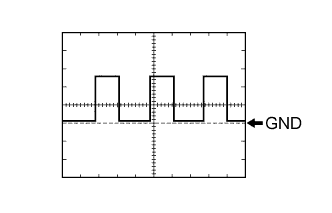
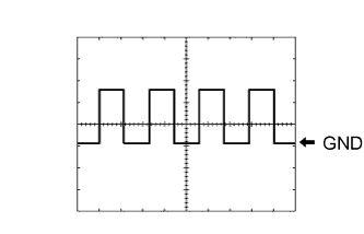
Waveform 1 (Reference) Item Condition Tester Connection - G19-5 (SI) - Body ground
- G19-6 (+S) - Body ground
Tool Setting 5 V/DIV., 20 msec./DIV. Condition Driving at approx. 20 km/h (12 mph) - HINT:
- As the vehicle speed increases, the wavelength shortens.
- G19-5 (SI) - Body ground
Using an oscilloscope, check waveform 2.
Waveform 2 (Reference) Item Condition Tester Connection G19-7 (S) - Body ground Tool Setting 5 V/DIV., 10 msec./DIV. Condition Engine idling - HINT:
- As the engine speed increases, the wavelength shortens.
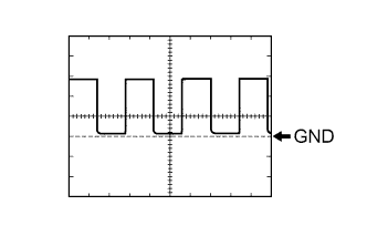
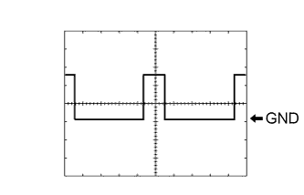
Using an oscilloscope, check waveform 3.
Waveform 3 (Reference) Item Condition Tester Connection G19-20 (SW) - Body ground Tool Setting 5 V/DIV., 50 msec./DIV. Condition Ignition switch ON, SRS warning light off Using an oscilloscope, check waveform 4.
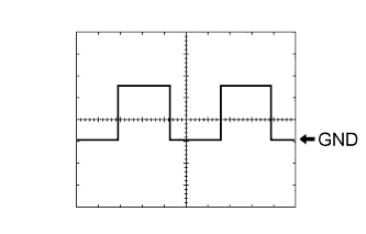
Waveform 4 (Reference) Item Condition Tester Connection G19-20 (SW) - Body ground Tool Setting 5 V/DIV., 50 msec./DIV. Condition Ignition switch ON, SRS warning light on Using an oscilloscope, check waveform 5.
Waveform 5 (Reference) Item Content Tester Connection G19-29 (FLVL) - Body ground Tool Setting 5 V/DIV., 200 msec./DIV. Condition Ignition switch ON, residual quantity of main fuel is 7.4L - HINT:
- No waveform is output during the period of time that begins 400 msec after the ignition switch is turned to ON and ends 800 msec after the ignition switch is turned to ON.
Using an oscilloscope, check waveform 6.
Waveform 6 (Reference) Item Content Tester Connection G19-29 (FLVL) - Body ground Tool Setting 5 V/DIV., 200 msec./DIV. Condition Ignition switch ON, residual quantity of main fuel is 71.2L - HINT:
- No waveform is output during the period of time that begins 400 msec after the ignition switch is turned to ON and ends 800 msec after the ignition switch is turned to ON.

| CHECK ACCESSORY METER (w/ Accessory Meter Assembly) |
 |
Disconnect the G32 accessory meter assembly connector.
Measure the voltage and resistance according to the value(s) in the table below.
Terminal No. (Symbol) Wiring Color Terminal Description Condition Specified Condition G32-1 (GND1) - Body ground LG - Body ground Ground Always Below 1 Ω G32-10 (SGND) - Body ground BR - Body ground Ground Always Below 1 Ω G32-12 (IG) - Body ground R-B - Body ground IG signal Ignition switch ON 11 to 14 V G32-12 (IG) - Body ground R-B - Body ground IG signal Ignition switch off Below 1 V G32-13 (ACC) - Body ground G-R - Body ground ACC signal Ignition switch ACC or ON 11 to 14 V G32-13 (ACC) - Body ground G-R - Body ground ACC signal Ignition switch off Below 1 V G32-14 (+B) - Body ground R - Body ground Battery Always 11 to 14 V Reconnect the G32 accessory meter connector.
Measure the voltage according to the value(s) in the table below.
*1: w/ Front Passenger Seat Belt Warning SystemTerminal No. (Symbol) Wiring Color Terminal Description Condition Specified Condition G32-2 (SG) - G32-3 (TH+) BR-Y - W-G Ambient temperature signal Ignition switch ON, ambient temperature 25°C (77°F) 1.32 V G32-2 (SG) - G32-3 (TH+) BR-Y - W-G Ambient temperature signal Ignition switch ON, ambient temperature 40°C (104°F) 0.8 V G32-8 (PBEW) - Body ground*1 G-W - Body ground Front passenger side seat belt warning light signal Ignition switch ON, front passenger side seat belt warning light on Below 1 V G32-8 (PBEW) - Body ground*1 G-W - Body ground Front passenger side seat belt warning light signal Ignition switch ON, front passenger side seat belt warning light off 11 to 14 V G32-11 (SW+) - Body ground*2 B - Body ground Steering pad switch signal Ignition switch ON, steering pad switch not pressed 4 V or more G32-11 (SW+) - Body ground*2 B - Body ground Steering pad switch signal Ignition switch ON, INFO switch pressed Below 1 V G32-11 (SW+) - Body ground*2 B - Body ground Steering pad switch signal Ignition switch ON, MODE RESET switch pressed 2 to 3 V
*2: w/ Steering Pad Switch
| COMBINATION METER INNER CIRCUIT |
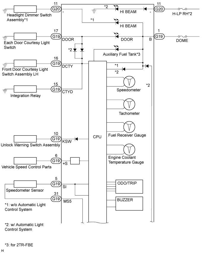
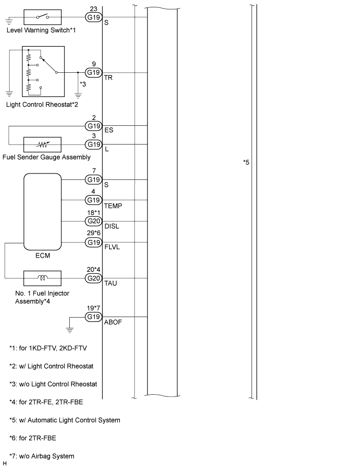
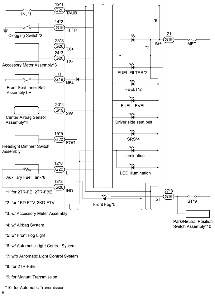
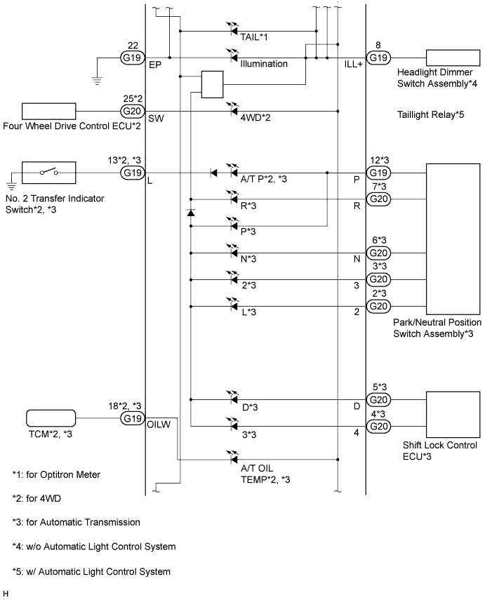
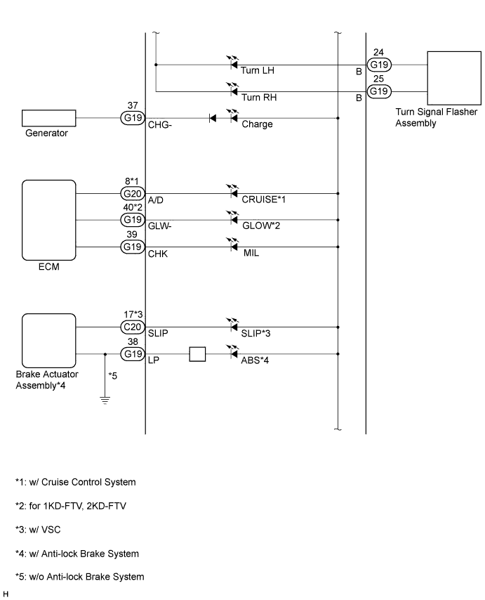
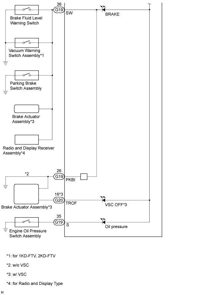
| TABLE OF TERMINAL CONNECTION |
*2: for Automatic Transmission
*3: for 4WD
*4: for 1KD-FTV, 2KD-FTV
*5: for Double Cab
*6: w/o Airbag System
*7: w/ Airbag System
*8: w/ VSC
*9: w/o VSC
*10: w/ Cruise Control System
*11: w/ Front Fog Light
*12: w/ Anti-lock Brake System
*13: w/o Anti-lock Brake System
*14: for 2TR-FE
*15: w/ Accessory Meter Assembly
*16: for Radio and Display Type
*17: for 2TR-FBE
*18: w/o Automatic Light Control System
*19: w/ Automatic Light Control System
*20: for Manual Transmission
*21: w/o Light Control Rheostat
| Terminal No. | Wire Harness Side | |
| G19 | 1 | DOME fuse |
| 2 | Fuel sender gauge | |
| 3 | Fuel sender gauge | |
| 4 | ECM | |
| 5 | Speedometer sensor | |
| 6 | 4-pulse output | |
| 7 | ECM | |
| 8 |
| |
| 9 |
| |
| 10 | Unlock warning switch assembly | |
| 11 | Front seat buckle switch RH | |
| 12 | Park/neutral position switch assembly*2 | |
| 13 | No. 2 transfer indicator switch (Neutral position switch)*2, *3 | |
| 14 | Fuel filter (Clogging switch)*4 | |
| 15 | Integration relay | |
| 16 | Front door courtesy light switch assembly RH | |
| 17 |
| |
| 18 | TCM*2, *3 | |
| 19 | Body ground*6 | |
| 20 | Center airbag sensor assembly*7 | |
| 21 | MET fuse | |
| 22 | Body ground | |
| 23 | Fuel filter (Level warning switch)*4 | |
| 24 | Turn signal flasher relay | |
| 25 | Turn signal flasher relay | |
| 26 |
| |
| 27 |
| |
| 28 | - | |
| 29 | ECM*17 | |
| 30 | - | |
| 31 | Speedometer sensor | |
| 32 | - | |
| 33 | - | |
| 34 | - | |
| 35 | Engine oil pressure switch assembly | |
| 36 |
| |
| 37 | Generator | |
| 38 |
| |
| 39 | ECM | |
| 40 | ECM*4 | |
| G20 | 1 | - |
| 2 | Park/neutral position switch assembly*2 | |
| 3 | Park/neutral position switch assembly*2 | |
| 4 | Shift lock control ECU*2 | |
| 5 | Shift lock control ECU*2 | |
| 6 | Park/neutral position switch assembly*2 | |
| 7 | Park/neutral position switch assembly*2 | |
| 8 | ECM*10 | |
| 9 | - | |
| 10 | - | |
| 11 |
| |
| 12 | Auxiliary fuel tank*17 | |
| 13 | Auxiliary fuel tank*17 | |
| 14 | - | |
| 15 | Headlight dimmer switch assembly*11 | |
| 16 | Brake actuator assembly*8 | |
| 17 | Brake actuator assembly*8 | |
| 18 | ECM*4 | |
| 19 | INJ fuse*14, *17 | |
| 20 | No. 1 fuel injector assembly*14, *17 | |
| 21 | - | |
| 22 | - | |
| 23 | Accessory meter assembly*15 | |
| 24 | Accessory meter assembly*15 | |
| 25 | Four wheel drive control ECU*3 | |
| 26 | - | |
| 27 | - | |
| 28 | - | |