Vehicle Interior. Hilux. Tgn26, 36 Kun25, 26, 35, 36 Ggn25
Door Lock. Hilux. Tgn26, 36 Kun25, 26, 35, 36 Ggn25
Power Door Lock Control System -- Terminals Of Ecu |
| CHECK DRIVER SIDE JUNCTION BLOCK ASSEMBLY |
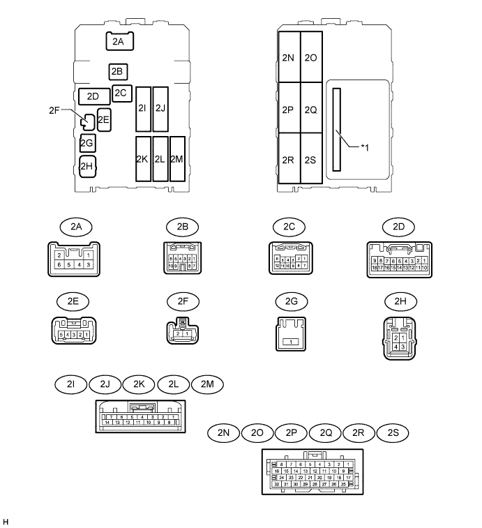
| *1 | Integration Relay | - | - |
Disconnect the 2D, 2H and 2L driver side junction block assembly connectors.
Measure the resistance and voltage according to the value(s) in the table below.
Terminal No. (Symbol) Wiring Color Terminal Description Condition Specified Condition 2D-9 (GND) - Body ground W-B - Body ground Ground Always Below 1 Ω 2D-18 (GND) - Body ground W-B - Body ground Ground Always Below 1 Ω 2H-4 (ALTB) - Body ground LG - Body ground Battery power supply Always 11 to 14 V 2L-12 (BECU) - Body ground L - Body ground Battery power supply Always 11 to 14 V - If the result is not as specified, there may be a malfunction on the wire harness side.
- If the result is not as specified, there may be a malfunction on the wire harness side.
Reconnect the 2D, 2H and 2L driver side junction block assembly connectors.
Measure the voltage according to the value(s) in the table below.
Terminal No. (Symbol) Wiring Color Terminal Description Condition Specified Condition 2A-4 (L1) - Body ground L - Body ground - Power window regulator master switch assembly (door control switch) lock input signal
- Driver side door key-linked lock input signal
- Power window regulator master switch assembly (door control switch) locked
- Driver side door key cylinder in lock position
Below 1 V - Power window regulator master switch assembly (door control switch) off
- Ignition switch off, all doors closed and driver side door key cylinder in neutral position
11 to 14 V 2D-4 (UL1) - Body ground L-W - Body ground - Power window regulator master switch assembly (door control switch) unlock input signal
- Driver side door key-linked unlock input signal
- Power window regulator master switch assembly (door control switch) unlocked
- Driver side door key cylinder in unlock position
Below 1 V - Power window regulator master switch assembly (door control switch) off
- Ignition switch off, all doors closed and driver side door key cylinder in neutral position
11 to 14 V 2K-10 (ACT-) - Body ground L-Y - Body ground Door lock motor unlock drive output signal (passenger door and rear RH door) Power window regulator master switch assembly (door control switch) not pushed and driver side door key cylinder in neutral position Below 1 V Lock side of power window regulator master switch assembly (door control switch) pushed, or driver side door key cylinder in unlock position 11 to 14 V 2K-11 (ACT+) - Body ground L - Body ground Door lock motor lock drive output signal (passenger door and rear RH door) Power window regulator master switch assembly (door control switch) not pushed and driver side door key cylinder in neutral position Below 1 V Lock side of power window regulator master switch assembly (door control switch) pushed, or driver side door key cylinder in lock position 11 to 14 V 2O-27 (DCTY) - Body ground R-B - Body ground Front door courtesy light switch assembly LH input signal Driver side door open Below 1 V Driver side door closed 11 to 14 V 2R-27 (ACT-) - Body ground L-Y - Body ground Door lock motor unlock drive output signal (driver door and rear LH door) Power window regulator master switch assembly (door control switch) not pushed and driver side door key cylinder in neutral position Below 1 V Lock side of power window regulator master switch assembly (door control switch) pushed, or driver side door key cylinder in unlock position 11 to 14 V 2R-28 (ACT+) - Body ground L - Body ground Door lock motor lock drive output signal (driver door and rear LH door) Power window regulator master switch assembly (door control switch) not pushed and driver side door key cylinder in neutral position Below 1 V Lock side of power window regulator master switch assembly (door control switch) pushed, or driver side door key cylinder in lock position 11 to 14 V - If the result is not as specified, the driver side junction block assembly may have a malfunction.
- Power window regulator master switch assembly (door control switch) lock input signal
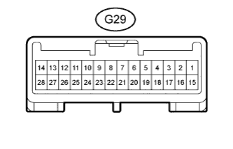
| CHECK THEFT WARNING ECU ASSEMBLY (w/ Theft Deterrent System) |
Disconnect the G29 theft warning ECU assembly connector.
Measure the resistance and voltage according to the value(s) in the table below.
Terminal No. (Symbol) Wiring Color Terminal Description Condition Specified Condition G29-1 (E) - Body ground B-W - Body ground Ground Always Below 1 Ω G29-4 (+B1) - Body ground L-Y - Body ground Battery power supply Always 11 to 14 V G29-14 (+B2) Body ground G - Body ground Battery power supply Always 11 to 14 V G29-18 (IG) Body ground R-L - Body ground Ignition power supply Ignition switch off Below 1 V Ignition switch ON 11 to 14 V - If the result is not as specified, there may be a malfunction on the wire harness side.
- If the result is not as specified, there may be a malfunction on the wire harness side.
Reconnect the G29 theft warning ECU assembly connector.
Measure the voltage according to the value(s) in the table below.
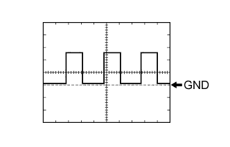
Terminal No. (Symbol) Wiring Color Terminal Description Condition Specified Condition G29-7 (CTY) - Body ground R-L - Body ground All Door courtesy switches input signal One or more doors open Below 1 V All doors closed 11 to 14 V G29-17 (SPD) - Body ground V-R - Body ground Vehicle speed input signal Driving at approximately 20 km/h (12.4 mph) Pulse generation (See waveform 1) - If the result is not as specified, the theft warning ECU assembly may have a malfunction.
- If the result is not as specified, the theft warning ECU assembly may have a malfunction.
Inspect using an oscilloscope.
- HINT:
- The waveform shown in the illustration is an example for reference only. Noise, chattering, etc. are not shown.
- As the vehicle speed increases, the wavelength shortens.
Waveform 1 (Reference)
Measurement Condition Item Content Tester Connection G29-17 (SPD) - Body ground Tool Setting 5 V/DIV., 10 msec./DIV. Condition Driving at approximately 20 km/h (12.4 mph)
 |