Rear View Monitor System (For Navigation Receiver Type) Reverse Signal Circuit
DESCRIPTION
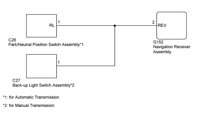
WIRING DIAGRAM
INSPECTION PROCEDURE
CHECK VEHICLE SIGNAL (OPERATION CHECK)
CHECK NAVIGATION RECEIVER ASSEMBLY
CHECK HARNESS AND CONNECTOR (NAVIGATION RECEIVER ASSEMBLY - PARK/NEUTRAL POSITION SWITCH ASSEMBLY)
CHECK HARNESS AND CONNECTOR (NAVIGATION RECEIVER ASSEMBLY - BACK-UP LIGHT SWITCH ASSEMBLY)
REAR VIEW MONITOR SYSTEM (for Navigation Receiver Type) - Reverse Signal Circuit |
DESCRIPTION
The navigation receiver assembly receives a reverse signal from the park/neutral position switch assembly*1 or back-up light switch assembly*2.- *1: for Automatic Transmission
- *2: for Manual Transmission
WIRING DIAGRAM
INSPECTION PROCEDURE
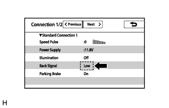
| 1.CHECK VEHICLE SIGNAL (OPERATION CHECK) |
Enter the "Function Check/Setting" screen and select "Connection status" (HILUX_TGN26 RM000003A3N01YX.html).
Check that the display changes between ON and OFF according to the shift lever position.
- OK:
Shift Lever Position
| Display
|
R
| High
|
Except R
| Low
|
- HINT:
- This display is updated once per second. As a result, it is normal for the display to lag behind the actual shift lever position.
| 2.CHECK NAVIGATION RECEIVER ASSEMBLY |
Disconnect the G152 navigation receiver assembly connector.
Measure the voltage according to the value(s) in the table below.
- Standard Voltage:
Tester Connection
| Condition
| Specified Condition
|
G152-2 (REV) - Body ground
| Ignition switch ON, shift lever in R
| 7.5 to 14 V
|
G152-2 (REV) - Body ground
| Ignition switch ON, shift lever not in R
| Below 1 V
|
Text in Illustration*a
| Front view of wire harness connector
(to Navigation Receiver Assembly)
|
ResultResult
| Proceed to
|
OK
| A
|
NG (for Automatic Transmission)
| B
|
NG (for Manual Transmission)
| C
|
| 3.CHECK HARNESS AND CONNECTOR (NAVIGATION RECEIVER ASSEMBLY - PARK/NEUTRAL POSITION SWITCH ASSEMBLY) |
Disconnect the G152 navigation receiver assembly connector.
Disconnect the C26 park/neutral position switch assembly connector.
Measure the resistance according to the value(s) in the table below.
- Standard Resistance:
Tester Connection
| Condition
| Specified Condition
|
G152-2 (REV) - C26-1 (RL)
| Always
| Below 1 Ω
|
G152-2 (REV) - Body ground
| Always
| 10 kΩ or higher
|
ResultResult
| Proceed to
|
OK (for A340F)
| A
|
OK (for A343E)
| B
|
OK (for A343F)
| C
|
NG
| D
|
| |
|
| |
|
| | REPAIR OR REPLACE HARNESS OR CONNECTOR |
|
|
| 4.CHECK HARNESS AND CONNECTOR (NAVIGATION RECEIVER ASSEMBLY - BACK-UP LIGHT SWITCH ASSEMBLY) |
Disconnect the G152 navigation receiver assembly connector.
Disconnect the C27 back-up light switch assembly connector.
Measure the resistance according to the value(s) in the table below.
- Standard Resistance:
Tester Connection
| Condition
| Specified Condition
|
G152-2 (REV) - C27-1
| Always
| Below 1 Ω
|
G152-2 (REV) - Body ground
| Always
| 10 kΩ or higher
|
ResultResult
| Proceed to
|
OK (for R151)
| A
|
OK (for R151F)
| B
|
NG
| C
|
| |
|
| | REPAIR OR REPLACE HARNESS OR CONNECTOR |
|
|