Vane Pump (For Kd Series Engine) Installation
Steering. Hilux. Tgn26, 36 Kun25, 26, 35, 36 Ggn25
INSTALL VANE PUMP ASSEMBLY
CONNECT PRESSURE FEED TUBE ASSEMBLY
CONNECT OIL RESERVOIR TO PUMP HOSE
ADD POWER STEERING FLUID
ADJUST POWER STEERING FLUID
CHECK FOR POWER STEERING FLUID LEAK
INSTALL FRONT SIDE MEMBER TO FRONT SUSPENSION CROSSMEMBER BRACE
INSTALL NO. 1 ENGINE UNDER COVER
INSTALL NO. 2 ENGINE UNDER COVER
INSTALL FRONT WHEEL LH
Vane Pump (For Kd Series Engine) -- Installation |
| 1. INSTALL VANE PUMP ASSEMBLY |
Coat a new O-ring with MP grease and install it to the vane pump.
Install the pump with the 2 nuts.
- Torque:
- 39 N*m{398 kgf*cm, 29 ft.*lbf}
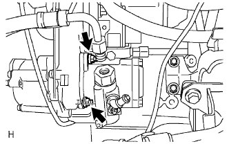
| 2. CONNECT PRESSURE FEED TUBE ASSEMBLY |
Using a union nut wrench, connect the tube to the vane pump.
Text in Illustration*1
| Union Nut Wrench
|
- Torque:
- 44 N*m{449 kgf*cm, 32 ft.*lbf}
- NOTICE:
- Use the formula to calculate special torque values for situations where a union nut wrench is combined with a torque wrench (HILUX_TGN26 RM000004QR1006X.html).
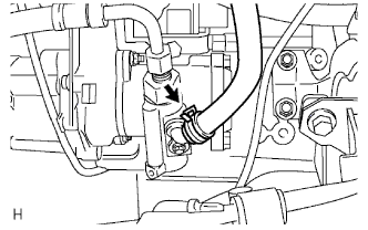
| 3. CONNECT OIL RESERVOIR TO PUMP HOSE |
Connect the oil reservoir to pump hose with the clip.
- HINT:
- Connect the pump side of the hose so that the paint mark faces the front of the vehicle.
- Make sure the claw of the clamp on the pump side faces the front of the vehicle.
Attach the 6 clips to install the front fender apron seal LH.
| 4. ADD POWER STEERING FLUID |
| 5. ADJUST POWER STEERING FLUID |
(HILUX_TGN26 RM00000138601PX.html)
| 6. CHECK FOR POWER STEERING FLUID LEAK |
| 7. INSTALL FRONT SIDE MEMBER TO FRONT SUSPENSION CROSSMEMBER BRACE |
Install the crossmember brace with the 8 bolts.
- Torque:
- 50 N*m{510 kgf*cm, 37 ft.*lbf}
| 8. INSTALL NO. 1 ENGINE UNDER COVER |
Install the engine under cover with the 4 bolts.
- Torque:
- 28 N*m{286 kgf*cm, 21 ft.*lbf}
| 9. INSTALL NO. 2 ENGINE UNDER COVER |
Install the engine under cover with the 4 bolts.
- Torque:
- 28 N*m{286 kgf*cm, 21 ft.*lbf}
| 10. INSTALL FRONT WHEEL LH |
- Torque:
- 105 N*m{1071 kgf*cm, 77 ft.*lbf}