Dtc C1249/49 Open In Stop Light Switch Circuit
Brake. Hilux. Tgn26, 36 Kun25, 26, 35, 36 Ggn25
DESCRIPTION
WIRING DIAGRAM
INSPECTION PROCEDURE
CHECK STOP LIGHT OPERATION
READ VALUE USING INTELLIGENT TESTER (STOP LIGHT SW)
RECONFIRM DTC
CHECK TERMINAL VOLTAGE (STP TERMINAL)
DTC C1249/49 Open in Stop Light Switch Circuit |
DESCRIPTION
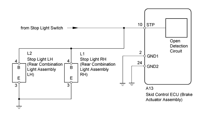
The skid control ECU (brake actuator assembly) has an open detection circuit, which outputs this DTC when detecting open circuits in the stop light input line of the stop light LH and RH circuits or an open in the ground line with the stop light switch off (brake pedal not depressed).DTC Code
| DTC Detection Condition
| Trouble Area
|
C1249/49
| When the IG1 terminal voltage is 9.5 V or higher, either condition continues for 0.3 seconds or more.
- Open circuits in the stop light LH and RH circuits.
- An open circuit in the ground line of the stop light LH and RH circuits.
| - Stop light switch circuit
- Stop light LH and RH circuits
- Skid control ECU (Brake actuator assembly)
|
WIRING DIAGRAM
INSPECTION PROCEDURE
- NOTICE:
- Before disconnecting the connector, make sure that there are no problems with the connection.
- After disconnecting the connector, make sure that the connector case and terminals are not deformed or corroded.
| 1.CHECK STOP LIGHT OPERATION |
Check that the stop light LH and RH come on when the brake pedal is depressed, and go off when the brake pedal is released.
- OK:
Condition
| Illumination Condition
|
Brake pedal depressed
| On
|
Brake pedal released
| Off
|
| 2.READ VALUE USING INTELLIGENT TESTER (STOP LIGHT SW) |
Turn the ignition switch off.
Connect the intelligent tester to the DLC3.
Turn the ignition switch to ON.
Turn the intelligent tester on.
Enter the following menus: Chassis / ABS/VSC/TRC / Data List.
ABS/VSC/TRCTester Display
| Measurement Item/Range
| Normal Condition
| Diagnostic Note
|
Stop Light SW
| Stop light switch / ON or OFF
| ON: Brake pedal depressed
OFF: Brake pedal released
| -
|
Using the intelligent tester, check the input of the stop light switch operation when the brake pedal is operated.
- OK:
- When the brake pedal is operated, the display changes as shown above.
Clear the DTC (HILUX_TGN26 RM000000XHV0CFX.html).
Turn the ignition switch off.
Start the engine.
Check if the same DTC is output (HILUX_TGN26 RM000000XHV0CFX.html).
ResultResult
| Proceed to
|
DTC not output
| A
|
DTC output
| B
|
- HINT:
- If troubleshooting has been carried out according to the problem symptoms table, refer back to the table and proceed to the next step (HILUX_TGN26 RM000000XHN0CQX.html).
| 4.CHECK TERMINAL VOLTAGE (STP TERMINAL) |
Turn the ignition switch off.
Disconnect the skid control ECU (brake actuator assembly) connector.
Measure the voltage according to the value(s) in the table below.
- Standard Voltage:
Tester Connection
| Condition
| Specified Condition
|
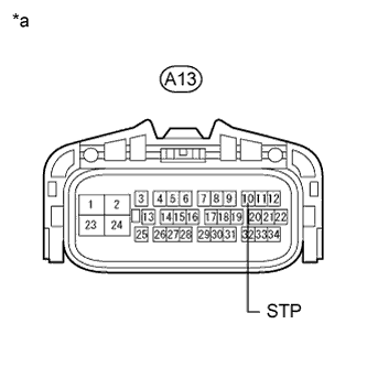
A13-10 (STP) - Body ground
| Brake pedal depressed
| 8 to 14 V
|
Brake pedal released
| Below 1.5 V
|
Text in Illustration*a
| Front view of wire harness connector
(to Skid Control ECU [Brake Actuator Assembly])
|
| | REPAIR OR REPLACE HARNESS OR CONNECTOR |
|
|