Anti-Lock Brake System -- Test Mode Procedure |
| TEST MODE PROCEDURE (SIGNAL CHECK) |
- HINT:
- After entering Test Mode, all Test Mode DTCs are stored. Then, during the signal check, the Test Mode DTCs for items which the skid control ECU (brake actuator assembly) determines to be normal are cleared.
- Once the vehicle returns to normal mode, all Test Mode DTCs are cleared.
Enter Test Mode (when using the intelligent tester).
Turn the ignition switch off.
Check that the steering wheel is in the straight-ahead position.
for Automatic Transmission:
Check that the shift lever is in P and apply the parking brake.
for Manual Transmission:
Check that the shift lever is in neutral and apply the parking brake.Connect the intelligent tester to the DLC3.
Turn the ignition switch to ON.
Turn the intelligent tester on.
Switch the skid control ECU to Test Mode using the intelligent tester.
Enter the following menus: Chassis / ABS/VSC/TRC / Utility / Signal Check.Check that the ABS warning light blinks in the Test Mode pattern (0.125 seconds on and 0.125 seconds off).
Enter Test Mode (when using SST check wire).
Turn the ignition switch off.
Check that the steering wheel is in the straight-ahead position.
for Automatic Transmission:
Check that the shift lever is in P and apply the parking brake.
for Manual Transmission:
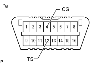
Check that the shift lever is in neutral and apply the parking brake.Using SST, connect terminals 12 (TS) and 4 (CG) of the DLC3.
- SST
- 09843-18040
- NOTICE:
- Do not connect the incorrect terminals as this will cause damage.
Text in Illustration *a Front view of DLC3 Turn the ignition switch to ON.
Check that the ABS warning light blinks in the Test Mode pattern (0.125 seconds on and 0.125 seconds off).
| ABS SIGNAL CHECK |
for 4WD and Pre-Runner:
Perform the deceleration sensor check.Enter Test Mode.
Keep the vehicle stationary on a level surface for 1 second or more.
for 4WD:
Perform the H2 to L4 shift operation check.Enter Test Mode.
Start the engine.
Move the transfer shift lever from the H2 position to the L4 position.
Move the transfer shift lever from the L4 position to the H2 position.
Speed Sensor Check
- NOTICE:
- The speed sensor check may not be completed if the speed sensor check is started while turning the steering wheel or spinning the wheels.
- After the ABS warning light goes off, if the vehicle speed exceeds 80 km/h (50 mph), a sensor check code is stored again. Decelerate or stop the vehicle before the vehicle speed reaches 80 km/h (50 mph).
- If the sensor check is not completed, the ABS warning light blinks while driving and the ABS does not operate.
Enter Test Mode.
Start the engine.
Drive the vehicle straight-ahead. Accelerate the vehicle to a speed of 45 km/h (28 mph) or more for several seconds.
Check that the ABS warning light goes off.
- HINT:
- The sensor check may not be completed if wheelspin occurs.
- The ABS warning light comes on immediately if a malfunction is detected during the speed sensor check.
Stop the vehicle.
- HINT:
- When the sensor check is completed, the ABS warning light goes off while driving and blinks in the Test Mode pattern (0.125 seconds on and 0.125 seconds off) while the vehicle is stationary.
| END OF SIGNAL CHECK |
If the signal check is completed, the ABS warning light blinks (0.125 seconds on and 0.125 seconds off) when the vehicle stops and the ABS warning light is off while the vehicle is being driven.
- NOTICE:
- If the signal check has not been completed, the ABS warning light blinks while driving and the ABS does not operate.
| READ DTC OF SIGNAL CHECK FUNCTION |
When using the intelligent tester:
Read the output DTC(s) by following the tester screen.
- NOTICE:
- If only DTCs other than Test Mode (signal check) DTCs are output, repair the malfunctions and clear the DTCs.
- If Test Mode (signal check) DTCs and other DTCs are output or if only Test Mode (signal check) DTCs are output, repair the malfunctions, clear the DTCs and Test Mode (signal check) DTCs, and perform the Test Mode (signal check) inspection again.
- HINT:
- Refer to the List of Test Mode (Signal Check) DTC.
Turn the ignition switch off and disconnect the intelligent tester.
When using SST check wire:
- NOTICE:
- When terminals 12 (TS) and 4 (CG) are not connected, do not turn the ignition switch off. If the ignition switch is turned off and then to ON again with no connection between terminals 12 (TS) and 4 (CG), the Test Mode DTCs are cleared.
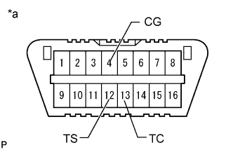
Using SST, connect terminals 12 (TS), 13 (TC) and 4 (CG) of the DLC3.
- SST
- 09843-18040
- NOTICE:
- Do not connect the incorrect terminals as this will cause damage.
Text in Illustration *a Front view of DLC3 Count the number of blinks of the ABS warning light.
- NOTICE:
- If only DTCs other than Test Mode sensor check DTCs are output, repair the malfunctions and clear the DTCs.
- If Test Mode (signal check) DTCs and other DTCs are output or if only Test Mode (signal check) DTCs are output, repair the malfunctions, clear the DTCs and Test Mode (signal check) DTCs, and perform the Test Mode (signal check) inspection again.
- HINT:
- If more than 1 malfunction is detected at the same time, the lowest numbered code is output first.
- Refer to the List of Test Mode (Signal Check) DTC.
Disconnect SST from terminals 12 (TS), 13 (TC) and 4 (CG) of the DLC3 and turn the ignition switch off.
Turn the ignition switch to ON.
- HINT:
- The Test Mode DTCs are cleared by turning the ignition switch to ON again.
Test Mode (Signal Check) DTC Memory Status Chart DLC3 Ignition switch ON Ignition switch off Ignition switch off → Ignition switch ON Terminals 12 (TS) and 4 (CG) connected DTC memory maintained DTC memory maintained DTC memory maintained Terminals 12 (TS) and 4 (CG) not connected DTC memory maintained DTC memory maintained DTC memory cleared
| LIST OF TEST MODE (SIGNAL CHECK) DTC |
- HINT:
- The codes in this table are output only in Test Mode (signal check).
| DTC Code | Detection Item | Trouble Area | |
| Intelligent Tester Display | ABS Warning Light Display | ||
| C1271 | 71 | Low output signal of front speed sensor RH |
|
| C1272 | 72 | Low output signal of front speed sensor LH |
|
| C1273 | 73 | Low output signal of rear speed sensor RH |
|
| C1274 | 74 | Low output signal of rear speed sensor LH |
|
| C1275 | 75 | Abnormal change in output signal of front speed sensor RH | Front skid control rotor RH |
| C1276 | 76 | Abnormal change in output signal of front speed sensor LH | Front skid control rotor LH |
| C1277 | 77 | Abnormal change in output signal of rear speed sensor RH | Rear skid control rotor RH |
| C1278 | 78 | Abnormal change in output signal of rear speed sensor LH | Rear skid control rotor LH |
| C1279 | 79 | Deceleration sensor output voltage malfunction |
|
| C1282* | 82* | 4WD detection switch (Center differential lock position switch) malfunction |
|
| C1283* | 83* | L4 position switch malfunction |
|
- *: for 4WD