Propeller Shaft Assembly (For Tmt Made) -- Reassembly |
| 1. INSTALL UNIVERSAL JOINT SPIDER ASSEMBLY |
- HINT:
- Use the same procedure for all universal joint spiders.
Apply MP grease to a new spider and 2 new spider bearings.
- NOTICE:
- Be careful not to apply too much grease.
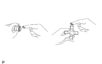 |
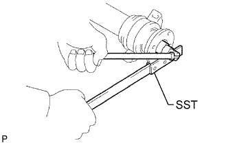
Fit the spider into the yoke.
Using SST, install the 2 spider bearings to the spider.
- SST
- 09332-25010
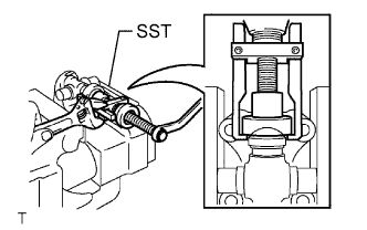 |
Using SST, adjust the spider bearings so that: 1) the yoke does not overlap the snap ring grooves of the spider bearings; 2) the grooves are as wide as possible; and 3) the groove width on both sides is the same.
- SST
- 09332-25010
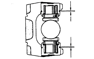 |
Install 2 new snap rings to the installed spider bearings. The snap rings must have equal thickness and allow 0 to 0.05 mm (0 to 0.00196 in.) of axial play.
- Standard Snap Ring Thickness:
Part No. Thickness Mark 90520-T0007 2.19 mm (0.0862 in.) F 90520-T0008 2.21 mm (0.0870 in.) G 90520-T0009 2.23 mm (0.0878 in.) H 90520-T0010 2.25 mm (0.0886 in.) J 90520-T0011 2.27 mm (0.0894 in.) K 90520-T0012 2.29 mm (0.0902 in.) 1 90520-T0013 2.31 mm (0.0909 in.) 2 90520-T0014 2.33 mm (0.0917 in.) 3 90520-T0015 2.35 mm (0.0925 in.) 4 90520-T0016 2.37 mm (0.0933 in.) 5 90520-T0017 2.39 mm (0.0941 in.) 6 90520-T0018 2.41 mm (0.0949 in.) 7 90520-T0019 2.43 mm (0.0957 in.) 8 90520-T0020 2.45 mm (0.0965 in.) N 90520-T0021 2.47 mm (0.0972 in.) 10 90520-T0022 2.49 mm (0.0980 in.) A 90520-T0023 2.51 mm (0.0988 in.) B 90520-T0024 2.53 mm (0.0996 in.) C 90520-T0025 2.55 mm (0.1004 in.) D 90520-T0026 2.57 mm (0.1012 in.) E
- NOTICE:
- New snap rings must be used.
- The snap ring thickness must be the same on both ends.
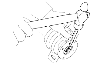
Using a plastic-faced hammer, tap the yoke until there is no clearance between the spider bearings and snap rings.
Text in Illustration *a Hammering Point
 |
Align the matchmarks on the yoke and shaft.
Install new spider bearings on the shaft side.
- HINT:
- Use the procedure described above.
| 2. INSPECT UNIVERSAL JOINT SPIDER ASSEMBLY |
Clamp the propeller shaft in a vise between aluminum plates.
- NOTICE:
- Do not overtighten the vise.
Check the spider bearings for wear or damage.
Check the axial play of each spider bearing by turning the yoke while holding the shaft tightly.
- Maximum bearing axial play:
- 0.05 mm (0.00196 in.)
 |
| 3. INSTALL CENTER NO. 1 SUPPORT BEARING ASSEMBLY |
Install the center support bearing to the intermediate shaft.
Text in Illustration *a Front Side
 |
Coat the splines of the intermediate shaft with MP grease.
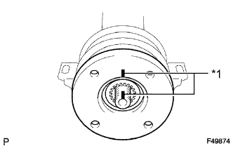
Align the matchmarks on the flange coupling and intermediate shaft, and install the flange coupling to the intermediate shaft.
Text in Illustration *1 Matchmark
 |
Install the washer.
Using SST to hold the flange coupling, press the bearing into position by installing a new lock nut.
- SST
- 09330-00021
- Torque:
- 181 N*m{1850 kgf*cm, 134 ft.*lbf}
 |
Loosen the lock nut.
Tighten the lock nut again.
- Torque:
- 68 N*m{700 kgf*cm, 51 ft.*lbf}
Using a chisel and hammer, stake the lock nut.
 |
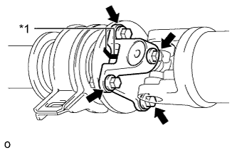
Completely remove any oil or the like and clean the contact surfaces of the propeller shaft flange and flange coupling.
Align the matchmarks on the flange yoke and flange coupling, and connect them with the 4 washers and 4 nuts.
Text in Illustration *1 Matchmark - Torque:
- 88 N*m{899 kgf*cm, 65 ft.*lbf}
- NOTICE:
- If any parts with matchmarks are replaced during inspection, reassemble them so that the yoke (for Pre-Runner: sleeve yoke; for 4WD: flange yoke) of the intermediate shaft and the rear flange yoke of the propeller shaft are at right angles to each other.
 |
| 4. INSPECT PROPELLER SHAFT GREASE FITTING DIRECTION |
- HINT:
- When replacing a spider bearing, be sure that the grease fitting hole is facing the direction shown in the illustration.
- Fill the grease fittings with MP grease.
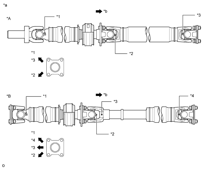
| *A | for Pre-Runner | *B | for 4WD |
| *1 | No. 1 Grease Fitting | *2 | No. 2 Grease Fitting |
| *3 | No. 3 Grease Fitting | *4 | No. 4 Grease Fitting |
| *a | Spider grease fitting assembly direction for propeller shaft assembly | *b | Rear Side |