Система Sfi 1Az-Fe -- Порядок Проведения Активной Диагностики |
- УКАЗАНИЕ:
- Только при использовании портативного диагностического прибора:
- Режим активной диагностики характеризуется лучшей, по сравнению с нормальным режимом, способностью обнаруживать неисправности. Следовательно, в режиме активной диагностики могут быть обнаружены неисправности, которые не могут быть обнаружены в нормальном режиме.
- ПРИМЕЧАНИЕ:
- Все сохраненные коды DTC и данные фиксированного набора параметров стираются в следующих случаях: 1) ECM переключается из нормального режима в режим активной диагностики или наоборот; 2) замок зажигания переключается из включенного положения (IG) в положение ACC или OFF (ВЫКЛ) во время режима активной диагностики. Поэтому, прежде чем изменить режим, обязательно проверьте и запишите DTC и данные фиксированного набора параметров.
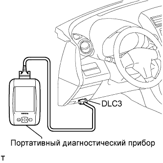
| ПОРЯДОК ВЫПОЛНЕНИЯ ПРОВЕРКИ В РЕЖИМЕ АКТИВНОЙ ДИАГНОСТИКИ (с помощью портативного диагностического прибора) |
Проверьте и обеспечьте выполнение следующих условий:
Положительное напряжение аккумуляторной батареи – не ниже 11 В.
Дроссельная заслонка полностью закрыта.
Рычаг переключения передач в положении "P" или "N".
Выключатель системы кондиционирования в положении OFF (ВЫКЛ)
Выключите зажигание.
Подсоедините портативный диагностический прибор к DLC3.
Включите зажигание (IG) и включите портативный диагностический прибор.
Выберите следующие элементы меню: Utility / Check Mode.
Переключите ECM из нормального режима диагностики в режим активной диагностики.
Удостоверьтесь, что контрольная лампа MIL магает, как показано на рисунке.
Запустите двигатель.
Убедитесь, что контрольная лампа MIL выключается.
Выполните проверку с имитацией условий возникновения неисправности, описанных клиентом.
Проверьте коды DTC и данные фиксированного набора параметров с помощью портативного диагностического прибора.
 |
 |
Front Propeller Shaft Assembly (For Tmt Made) -- Disassembly |
| 1. REMOVE UNIVERSAL JOINT SPIDER ASSEMBLY |
 |
- HINT:
- Use the same procedure for both universal joint spiders.
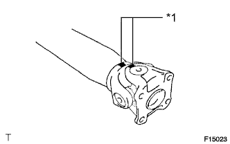
Place matchmarks on the flange yoke and propeller shaft.
Text in Illustration *1 Matchmark
Using a brass bar and hammer, slightly tap in the spider bearing outer races.
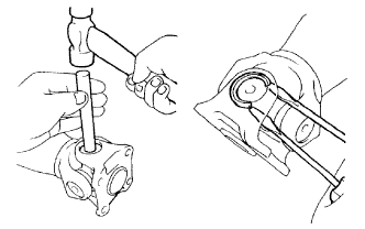 |
Using 2 screwdrivers, remove the 4 snap rings from the grooves.
Clamp the propeller shaft in a vise between aluminum plates.
- NOTICE:
- Do not overtighten the vise.
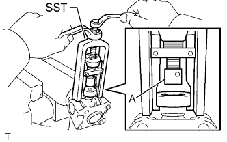 |
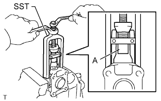
Using SST, push the sleeve yoke side spider bearing until: 1) the spider almost touches the sleeve yoke or propeller shaft, and 2) the spider bearing on the opposite side is partially pushed out.
- SST
- 09332-25010
- HINT:
- Before installing SST, sufficiently raise the part labeled A. If part A is too low, SST may be difficult to install.
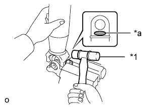
Clamp the pushed out spider bearing outer race in a vise between aluminum plates and tap the propeller shaft to remove the spider bearing.
Text in Illustration *1 Plastic-faced Hammer *a Hammering Point - NOTICE:
- Do not tap the shaft tube.
- Do not overtighten the vise.
- HINT:
- Use the same procedure to remove the spider bearing from the opposite side of the spider.
 |
Separate the flange yoke and spider from the propeller shaft.
Reinstall the 2 removed spider bearings to the spider and clamp the spider bearings in a vise between aluminum plates.
- NOTICE:
- Do not overtighten the vise.
 |
Using SST, push the flange yoke side spider bearing until: 1) the spider almost touches the flange yoke, and 2) the spider bearing on the opposite side is partially pushed out.
- SST
- 09332-25010
- HINT:
- Before installing SST, sufficiently raise the part labeled A. If part A is too low, SST may be difficult to install.
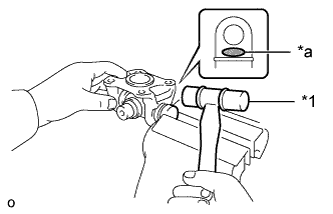
Clamp the pushed out spider bearing outer race in a vise between aluminum plates and tap the flange yoke to remove the spider bearing.
Text in Illustration *1 Plastic-faced Hammer *a Hammering Point - NOTICE:
- Do not overtighten the vise.
- HINT:
- Use the same procedure to remove the spider bearing from the opposite side of the spider.
 |
Separate the spider from the flange yoke.