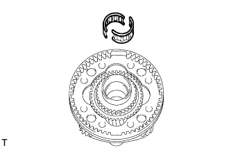
INSTALL TRANSFER LOW PLANETARY GEAR ASSEMBLY WITH TRANSFER INPUT SHAFT
INSTALL REAR TRANSFER OUTPUT SHAFT, TRANSFER FRONT DRIVE CHAIN AND TRANSFER DRIVEN SPROCKET
INSTALL TRANSFER INDICATOR SWITCH (NEUTRAL POSITION) (for Automatic Transmission)
Transfer Assembly -- Reassembly |
| 1. INSTALL TRANSFER DRIVE SPROCKET SUB-ASSEMBLY |
Apply gear oil to the connecting areas of the front drive clutch sleeve and transfer drive sprocket sub-assembly.
Text in Illustration *a Shifting key spring opening
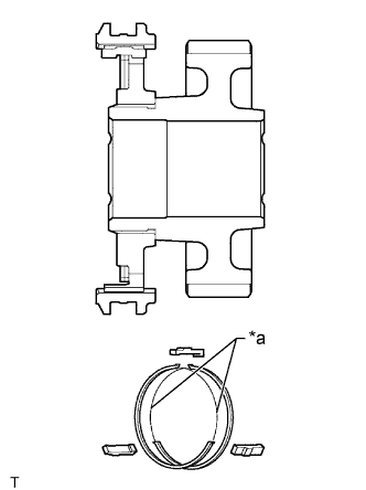 |
Install the front drive clutch sleeve, 3 shifting keys and 2 shifting key springs to the transfer drive sprocket sub-assembly.
- NOTICE:
- Install the front drive clutch sleeve in the correct direction.
- Install the shifting key springs so that their openings do not overlap as shown in the illustration.
- Make sure that the shifting key springs are firmly connected to the shifting keys.
- Make sure that the front drive clutch sleeve and transfer drive sprocket sub-assembly move smoothly.
Apply gear oil to the taper cone side of the front transfer drive clutch synchronizer ring and rear transfer output shaft.
Install front transfer drive clutch synchronizer ring to the transfer drive sprocket sub-assembly with front drive clutch sleeve.
 |
Apply gear oil to the needle roller bearing, and then install it to the transfer drive sprocket sub-assembly with front drive clutch sleeve.
Install the transfer drive sprocket sub-assembly with front drive clutch sleeve to the rear transfer output shaft.
Install the ball. Then install the spacer so that the spacer is aligned with the ball.
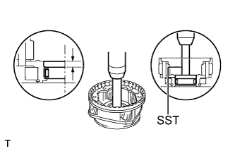
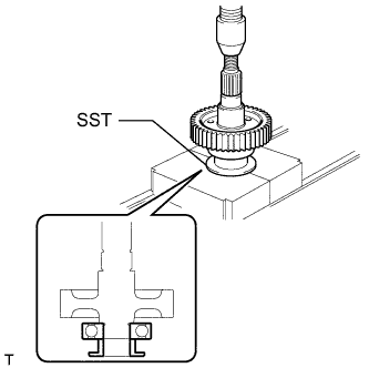
| 2. INSTALL REAR TRANSFER OUTPUT SHAFT RADIAL BALL BEARING |
Apply gear oil to the connecting areas of the rear transfer output shaft and rear transfer output shaft radial ball bearing.
Using SST and a press, press in a new rear transfer output shaft radial ball bearing to the rear transfer output shaft.
- NOTICE:
- Install the bearing in the correct direction.
Text in Illustration *1 Groove - SST
- 09316-60011(09316-00011,09316-00071)
 |
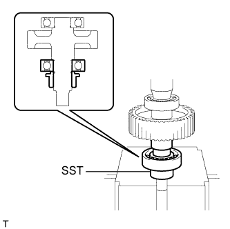
| 3. CHECK TRANSFER DRIVE SPROCKET THRUST CLEARANCE |
Using a feeler gauge, measure the thrust clearance.
- Standard thrust clearance:
- 0.10 to 0.25 mm (0.00394 to 0.00984 in.)
- Maximum thrust clearance:
- 0.25 mm (0.00984 in.)
 |
| 4. INSTALL TRANSFER HIGH AND LOW CLUTCH SLEEVE |
Apply gear oil to the connecting areas of the transfer high and low clutch sleeve and transfer clutch hub.
Text in Illustration *a Shifting key spring opening
 |
for Automatic Transmission:
Install the transfer high and low clutch sleeve to the transfer clutch hub.- NOTICE:
- Install the transfer high and low clutch sleeve in the correct direction.
- Make sure that the transfer high and low clutch sleeve and transfer clutch hub move smoothly.
for Manual Transmission:
Install the transfer high and low clutch sleeve, 3 shifting keys and 2 shifting key springs to the transfer clutch hub.- NOTICE:
- Install the transfer high and low clutch sleeve in the correct direction.
- Install the shifting key springs so that their openings do not overlap as shown in the illustration.
- Make sure that the shifting key springs are firmly connected to the shifting keys.
- Make sure that the transfer high and low clutch sleeve and transfer clutch hub move smoothly.
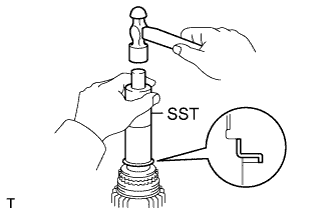
| 5. INSTALL TRANSFER CLUTCH HUB |
M/T:
Apply gear oil to the connecting areas of a new key retainer and the output shaft.
Using SST and a hammer, tap in the key retainer.
- SST
- 09316-60011(09316-00011)
- NOTICE:
- Be careful not to deform or damage the key retainer.
Apply gear oil to the connecting areas of the clutch hub and output shaft.
Using a press, press in the transfer clutch hub.
 |
| 6. INSTALL TRANSFER OUTPUT SHAFT SNAP RING |
Select a new snap ring that allows the minimum axial free play.
- Snap Ring Thickness:
Mark Specified Condition K 2.00 to 2.05 mm (0.0788 to 0.0807 in.) L 2.05 to 2.10 mm (0.0808 to 0.0826 in.) A 2.10 to 2.15 mm (0.0827 to 0.0846 in.) B 2.15 to 2.20 mm (0.0847 to 0.0866 in.) C 2.20 to 2.25 mm (0.0867 to 0.0885 in.) D 2.25 to 2.30 mm (0.0886 to 0.0905 in.) E 2.30 to 2.35 mm (0.0906 to 0.0925 in.) F 2.35 to 2.40 mm (0.0926 to 0.0944 in.) G 2.40 to 2.45 mm (0.0945 to 0.0964 in.) H 2.45 to 2.50 mm (0.0965 to 0.0984 in.) J 2.50 to 2.55 mm (0.0985 to 0.1004 in.)
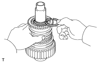 |
Using a snap ring expander, install the snap ring.
- NOTICE:
- Make sure that the snap ring is firmly installed to the groove.
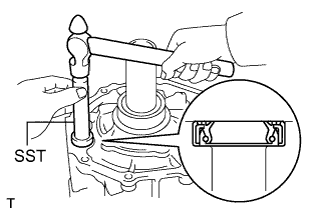
| 7. INSTALL TRANSFER LOW PLANETARY GEAR BEARING |
Using SST and a press, press in a new transfer low planetary gear bearing.
- SST
- 09950-60010(09951-00570)
09950-70010(09951-07100)
- Standard depth:
- 8.2 to 8.8 mm (0.323 to 0.346 in.)
 |
| 8. INSTALL TRANSFER INPUT SHAFT BEARING |
Using SST and a press, press in a new transfer input shaft bearing with the groove facing forward.
- SST
- 09223-15020
09515-30010
09950-70010(09951-07100)
 |
| 9. INSTALL TRANSFER INPUT BEARING SHAFT SNAP RING |
Select a new snap ring that allows 0.1 mm (0.00393 in.) or less of axial free play.
- Snap Ring Thickness:
Mark Specified Condition 1 1.45 to 1.50 mm (0.0571 to 0.0590 in.) 2 1.50 to 1.55 mm (0.0591 to 0.0610 in.) 3 1.55 to 1.60 mm (0.0611 to 0.0629 in.) 4 1.60 to 1.65 mm (0.0630 to 0.0649 in.) 5 1.65 to 1.70 mm (0.0650 to 0.0669 in.)
 |
Using a snap ring expander, install the snap ring.
- NOTICE:
- Make sure that the snap ring is firmly installed to the groove.
| 10. INSTALL NO. 1 TRANSFER INPUT SHAFT SEAL RING |
Apply gear oil to the 2 new No. 1 transfer input shaft seal rings, and then install them to the transfer input shaft.
- NOTICE:
- When installing the seal ring, make sure not to expand it so that its inner diameter exceeds 65 mm (2.55 in.).
 |
| 11. INSTALL TRANSFER INPUT SHAFT |
Install the bearing to the transfer low planetary gear assembly.
Text in Illustration *1 Transfer Low Planetary Gear Bearing *2 No. 1 Transfer Thrust Bearing Race - NOTICE:
- Install the bearing in the correct direction.
 |
Install the No. 1 transfer thrust bearing race to the transfer low planetary gear assembly.
Apply gear oil to the contact surfaces of the transfer input shaft and transfer low planetary gear assembly.
Install the transfer input shaft to the transfer low planetary gear assembly.
Apply gear oil to the manual transfer planetary carrier washer.
 |
Install the manual transfer planetary carrier washer to the transfer low planetary gear assembly.
Install the transfer input gear stopper ball to the transfer input shaft.
Install the transfer input gear stopper to the transfer input shaft.
| 12. INSTALL TRANSFER INPUT GEAR STOPPER SHAFT SNAP RING |
Select a new transfer input gear stopper shaft snap ring that allows 0.05 to 0.15 mm (0.00197 to 0.00590 in.) of axial free play.
- Snap Ring Thickness:
Mark Specified Condition A 2.10 to 2.15 mm (0.0827 to 0.0846 in.) B 2.15 to 2.20 mm (0.0847 to 0.0866 in.) C 2.20 to 2.25 mm (0.0867 to 0.0885 in.) D 2.25 to 2.30 mm (0.0886 to 0.0905 in.) E 2.30 to 2.35 mm (0.0906 to 0.0925 in.) F 2.35 to 2.40 mm (0.0926 to 0.0944 in.) G 2.40 to 2.45 mm (0.0945 to 0.0964 in.) H 2.45 to 2.50 mm (0.0965 to 0.0984 in.) J 2.50 to 2.55 mm (0.0985 to 0.100 in.) K 2.55 to 2.60 mm (0.101 to 0.102 in.) L 2.60 to 2.65 mm (0.103 to 0.104 in.) M 2.65 to 2.70 mm (0.105 to 0.106 in.) N 2.70 to 2.75 mm (0.107 to 0.108 in.) P 2.75 to 2.80 mm (0.109 to 0.110 in.) Q 2.80 to 2.85 mm (0.111 to 0.112 in.) R 2.85 to 2.90 mm (0.113 to 0.114 in.) S 2.90 to 2.95 mm (0.115 to 0.116 in.) T 2.95 to 3.00 mm (0.117 to 0.118 in.) U 3.00 to 3.05 mm (0.119 to 0.120 in.)
 |
Using a snap ring expander, install the snap ring.
- NOTICE:
- Make sure that the snap ring is firmly installed to the groove.
| 13. INSTALL FRONT TRANSFER OUTPUT SHAFT NEEDLE ROLLER BEARING |
Apply gear oil to the front transfer output shaft needle roller bearing, and then install it to the transfer low planetary gear assembly.
 |
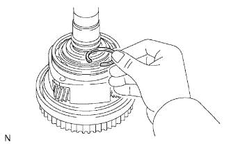
| 14. INSTALL TRANSFER LOW PLANETARY GEAR SPLINE PIECE |
Install the transfer low planetary gear spline piece to the transfer low planetary gear assembly.
 |
Using a screwdriver with its tip wrapped with protective tape, install the snap ring.
- NOTICE:
- Be careful not to damage the transfer low planetary gear assembly.
 |
| 15. INSTALL TRANSFER CASE OIL SEAL |
Using SST and a hammer, tap in 2 new transfer case oil seals until their surfaces are flush with the case upper surface.
- SST
- 09304-12012
- Standard depth:
- -0.5 to 0.5 mm (-0.0196 to 0.0196 in.)
- NOTICE:
- Be careful not to damage the front transfer case.
 |
Coat the lip of each oil seal with MP grease.
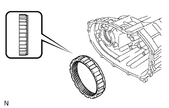
| 16. INSTALL TRANSFER LOW PLANETARY RING GEAR |
Install the transfer low planetary ring gear to the front transfer case.
- NOTICE:
- Install the ring gear in the correct direction.
 |
Using a screwdriver with its tip wrapped with protective tape, install the snap ring.
- NOTICE:
- Make sure that the snap ring is firmly installed to the groove.
 |
| 17. INSTALL TRANSFER CASE PLUG |
Install the pin and compression spring to the front transfer case.
Apply adhesive to the threads of the transfer case plug, and then install it to the front transfer case.
- Adhesive:
- Toyota Genuine Adhesive 1344, Three Bond 1344 or equivalent
- Torque:
- 19 N*m{190 kgf*cm, 14 ft.*lbf}
 |
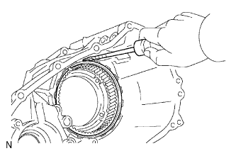
| 18. INSTALL TRANSFER LOW PLANETARY GEAR ASSEMBLY WITH TRANSFER INPUT SHAFT |
Install the transfer low planetary gear assembly with transfer input shaft.
- HINT:
- If necessary, heat the front case to about 50 to 80°C (122 to 176°F).
 |
Using a snap ring expander, install the snap ring.
- NOTICE:
- Make sure that the snap ring is firmly installed to the groove.
 |
| 19. INSTALL FRONT TRANSFER DRIVE CLUTCH SYNCHRONIZER RING |
Apply gear oil to the front transfer drive clutch synchronizer ring taper cone side, and then install it to the transfer input shaft.
 |
| 20. INSTALL TRANSFER OIL PUMP GEAR |
Apply gear oil to the sliding surface of the transfer oil pump gear.
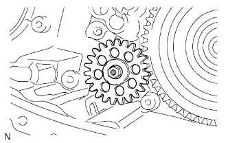 |
Install the transfer oil pump gear.
| 21. INSTALL TRANSFER OIL PUMP BODY O-RING |
Coat a new O-ring with gear oil and install it to the transfer oil pump body.
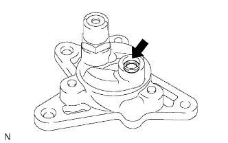 |
| 22. INSTALL TRANSFER OIL PUMP BODY SUB-ASSEMBLY |
Install the transfer oil pump body sub-assembly with the 3 bolts.
- Torque:
- 7.5 N*m{76 kgf*cm, 66 in.*lbf}
 |
| 23. INSTALL TRANSFER CASE MAGNET |
| 24. INSTALL TRANSFER OIL SEPARATOR SUB-ASSEMBLY |
Install the oil separator with the 3 bolts.
- Torque:
- 7.5 N*m{76 kgf*cm, 66 in.*lbf}
 |
| 25. INSTALL FILLER PLUG |
Install a new gasket and the filler plug.
- Torque:
- 37 N*m{377 kgf*cm, 27 ft.*lbf}
| 26. INSTALL DRAIN PLUG |
Install a new gasket and the drain plug.
- Torque:
- 37 N*m{377 kgf*cm, 27 ft.*lbf}
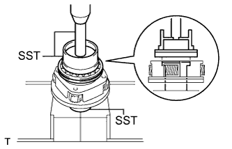
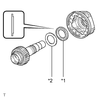
| 27. INSTALL TRANSFER INPUT GEAR RADIAL BALL BEARING |
Apply gear oil to the contact surfaces of a new transfer input gear radial ball bearing and the transfer driven sprocket.
 |
Using SST and a press, press in the transfer input gear radial ball bearing.
- SST
- 09316-60011(09316-00031)
- NOTICE:
- After press-fitting the bearing to the transfer driven sprocket, check that the bearing moves smoothly.
| 28. INSTALL TRANSFER DRIVEN SPROCKET BEARING |
Apply gear oil to the contact surfaces of a new transfer driven sprocket bearing and transfer driven sprocket.
 |
Using SST and a press, press in the transfer driven sprocket bearing.
- SST
- 09316-60011(09316-00071)
- NOTICE:
- After press-fitting the bearing to the transfer driven sprocket, check that the bearing moves smoothly.
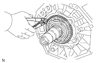
| 29. INSTALL REAR TRANSFER OUTPUT SHAFT, TRANSFER FRONT DRIVE CHAIN AND TRANSFER DRIVEN SPROCKET |
Mount the rear transfer case in a vise.
Text in Illustration *1 Aluminum Plate - NOTICE:
- Place aluminum plates on the vise to prevent damage to the rear transfer case.
 |
Install the rear transfer output shaft and transfer driven sprocket to the front drive chain.
Install the rear transfer output shaft together with the front transfer drive chain and transfer driven sprocket to the rear transfer case.
- NOTICE:
- When installing the rear transfer output shaft, make sure that the installation of the synchronizer ring, sleeve and shifting keys is not affected.
- HINT:
- Check that the output shaft and driven sprocket turn smoothly.
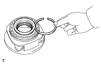
Using a snap ring expander, install the snap ring.
- NOTICE:
- Make sure that the snap ring is firmly installed to the groove.
 |
| 30. INSTALL TRANSFER HIGH AND LOW SHIFT FORK SHAFT |
Apply gear oil to the connecting areas of the transfer high and low shift fork shaft and each part.
 |
Install the transfer high and low shift fork shaft and No. 2 transfer gear shift fork.
- NOTICE:
- Install the transfer high and low shift fork shaft and No. 2 transfer gear shift fork in the correct directions.
Install the ball and spring to the hole.
Apply adhesive to the threads of the plug.
- Adhesive:
- Toyota Genuine Adhesive 1344, Three Bond 1344 or equivalent
Using a hexagon wrench, install the plug.
- Torque:
- 19 N*m{190 kgf*cm, 14 ft.*lbf}
| 31. INSTALL FRONT TRANSFER DRIVE SHIFT FORK SHAFT |
Apply gear oil to the straight pin and install it to the hole of the rear transfer case.
 |
Apply gear oil to the connecting areas of the front transfer drive shift fork shaft and each part.
 |
Install the front transfer drive shift fork shaft, spring, No. 1 transfer gear shift fork and shift shaft stopper.
- NOTICE:
- Install the front transfer drive shift fork shaft, No. 1 transfer gear shift fork and shift shaft stopper in the correct directions.
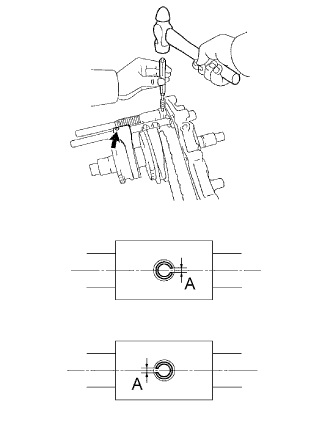
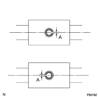
Using a pin punch and hammer, install the 2 slotted pins.
- NOTICE:
- When installing the slotted pins, make sure that groove A of the pin is facing in the same direction as the shaft.
 |
Install the ball and spring to the hole of the rear transfer case.
Apply adhesive to the threads of the plug.
- Adhesive:
- Toyota Genuine Adhesive 1344, Three Bond 1344 or equivalent
Using a hexagon wrench, install the plug.
- Torque:
- 19 N*m{190 kgf*cm, 14 ft.*lbf}
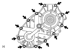
| 32. INSTALL REAR TRANSFER CASE |
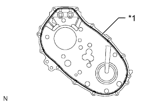
Remove any old seal packing and be careful not to spill oil on the contact surfaces of the front transfer case and rear transfer case.
Apply seal packing to the rear case as shown in the illustration.
- Seal packing:
- Toyota Genuine Seal Packing 1281, Three Bond 1281 or equivalent
Text in Illustration *1 Seal Packing
 |
Install the clamp and rear case with the 12 bolts.
- Torque:
- 28 N*m{286 kgf*cm, 21 ft.*lbf}
- NOTICE:
- Tighten the bolts of the rear case within 10 minutes of applying the seal packing. The seal packing will dry very quickly.
 |
| 33. INSTALL TRANSFER SPEEDOMETER DRIVE GEAR |
Install the ball and transfer speedometer drive gear to the rear transfer output shaft.
| 34. INSTALL TRANSFER OUTPUT SHAFT WASHER |
Install the 2 transfer output washers to the rear transfer output shaft.
| 35. INSTALL TRANSFER EXTENSION HOUSING SUB-ASSEMBLY |
Remove any old seal packing and be careful not to spill oil on the contact surfaces of the transfer extension housing sub-assembly and rear transfer case.
Apply seal packing to the transfer extension housing sub-assembly as shown in the illustration.
- Seal packing:
- Toyota Genuine Seal Packing 1281, Three Bond 1281 or equivalent
Text in Illustration *1 Seal Packing
 |
Apply adhesive to the threads of the bolts.
- Adhesive:
- Toyota Genuine Adhesive 1344, Three Bond 1344 or equivalent
Install the transfer extension housing sub-assembly with the 5 bolts.
- Torque:
- 12 N*m{122 kgf*cm, 9 ft.*lbf}
- NOTICE:
- Tighten the bolts of the transfer extension housing sub-assembly within 10 minutes of applying the seal packing. The seal packing will dry very quickly.
| 36. INSTALL SPEEDOMETER SENSOR |
Coat a new O-ring with gear oil and install it to the speedometer sensor.
Install the speedometer sensor to the transfer with the bolt.
- Torque:
- 12 N*m{117 kgf*cm, 8 ft.*lbf}
Connect the sensor connector.
| 37. INSTALL TRANSFER CASE OIL SEAL |
Coat the lip of a new oil seal with MP grease.
Using SST and a hammer, tap in the oil seal until its metal ring contacts the case.
- SST
- 09649-17010
09950-70010(09951-07100)
 |
| 38. INSTALL EXTENSION HOUSING OIL SEAL |
Coat the lip of a new oil seal with MP grease.
Using SST and a hammer, tap in the oil seal until its surface is flush with the housing upper surface.
- SST
- 09316-60011(09316-00011)
 |
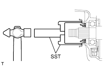
| 39. INSTALL FRONT OUTPUT SHAFT COMPANION FLANGE SUB-ASSEMBLY |
Using SST and a hammer, tap in a new oil seal to the front output shaft companion flange sub-assembly.
- SST
- 09950-60010(09951-00320)
09950-70010(09951-07100)
- NOTICE:
- Be careful not to damage the companion flange.
 |
Apply gear oil to the connecting areas of the front output shaft companion flange sub-assembly and transfer driven sprocket.
Install the front output shaft companion flange sub-assembly to the transfer driven sprocket.
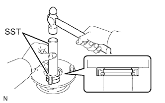
Using SST to hold the companion flange, install a new lock nut.
- SST
- 09330-00021
- Torque:
- 118 N*m{1203 kgf*cm, 87 ft.*lbf}
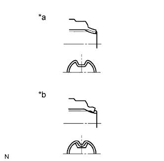
Using a chisel and hammer, stake the lock nut.
Text in Illustration *a CORRECT *b INCORRECT - NOTICE:
- Securely stake the shaft to the lock nut groove.
- Be careful not to damage parts around the lock nut.
- Do not apply excessive force to the shaft.
 |
| 40. INSTALL REAR OUTPUT SHAFT COMPANION FLANGE SUB-ASSEMBLY |
Using SST and a hammer, tap in a new oil seal to the rear output shaft companion flange sub-assembly.
- SST
- 09950-60010(09951-00320)
09950-70010(09951-07100)
- NOTICE:
- Be careful not to damage the companion flange.
|
Apply gear oil to the connecting areas of the rear output shaft companion flange and rear transfer output shaft.
Using SST, install the rear output shaft companion flange sub-assembly in the same way as the front output shaft companion flange.
- SST
- 09330-00021
- Torque:
- 118 N*m{1203 kgf*cm, 87 ft.*lbf}
| 41. INSTALL BREATHER OIL DEFLECTOR SUB-ASSEMBLY |
| 42. INSTALL TRANSFER CASE COVER SUB-ASSEMBLY |
Install the transfer case cover sub-assembly with the 4 bolts.
- Torque:
- 18 N*m{184 kgf*cm, 13 ft.*lbf}
| 43. INSTALL TRANSFER BEARING RETAINER OIL SEAL |
Using SST and a hammer, tap in a new transfer bearing retainer oil seal until its surface is flush with the bearing retainer upper surface.
- SST
- 09950-60010(09951-00590)
09950-70010(09951-07100)
- NOTICE:
- Be careful not to damage the bearing retainer.
 |
Coat the lip of the oil seal with MP grease.
| 44. INSTALL TRANSFER BEARING RETAINER SUB-ASSEMBLY |
Remove any old seal packing and be careful not to spill oil on the contact surfaces of the transfer bearing retainer sub-assembly and front transfer case.
Apply seal packing to the transfer bearing retainer sub-assembly as shown in the illustration.
- Seal packing:
- Toyota Genuine Seal Packing 1281, Three Bond 1281 or equivalent
Text in Illustration *1 Seal Packing
 |
Apply adhesive to the bolt threads.
- Adhesive:
- Toyota Genuine Adhesive 1344, Three Bond 1344 or equivalent
Install the transfer bearing retainer sub-assembly with the 5 bolts.
- Torque:
- 12 N*m{117 kgf*cm, 8 ft.*lbf}
- NOTICE:
- Tighten the bolts of the bearing retainer within 10 minutes of applying the seal packing. The seal packing will dry very quickly.
| 45. INSTALL TRANSFER GEAR SHIFT HEAD |
Install the No. 1 and No. 2 transfer gear shift heads to the front transfer drive shift fork shaft and transfer high and low shift fork shaft.
Text in Illustration *1 Slotted Pin *2 No. 1 Gear Shift Head *3 No. 2 Gear Shift Head *4 Front Drive Shift Fork Shaft *5 High and Low Shift Fork Shaft
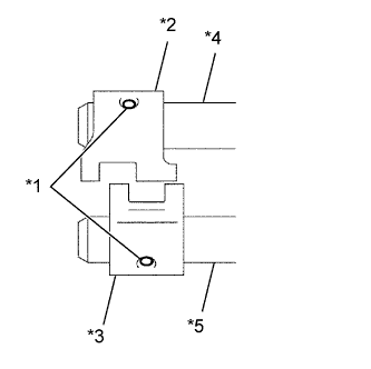 |
Using a pin punch and hammer, tap in the 2 slotted pins to the No. 1 and No. 2 transfer gear shift heads.
- NOTICE:
- When installing the slotted pins, make sure the pin groove labeled A is facing in the same direction as the shaft.
 |
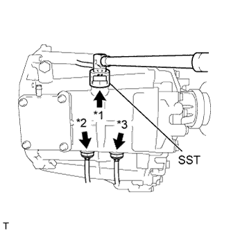
| 46. INSTALL TRANSFER INDICATOR SWITCH (NEUTRAL POSITION) (for Automatic Transmission) |
Using SST, install a new gasket and the transfer indicator switch.
- SST
- 09817-16011
- Torque:
- 37 N*m{377 kgf*cm, 27 ft.*lbf}
| 47. INSTALL TRANSFER INDICATOR SWITCH (L4 POSITION) (for Automatic Transmission or Manual Transmission w/ ABS) |
Using SST, install a new gasket and the transfer indicator switch.
- SST
- 09817-16011
- Torque:
- 37 N*m{377 kgf*cm, 27 ft.*lbf}
| 48. INSTALL TRANSFER INDICATOR SWITCH (4WD POSITION) |
Using SST, install a new gasket and the transfer indicator switch.
Text in Illustration *1 4WD Position *2 L4 Position *3 Neutral Position - SST
- 09817-16011
- Torque:
- 37 N*m{377 kgf*cm, 27 ft.*lbf}
 |