Clutch Pedal -- Installation |
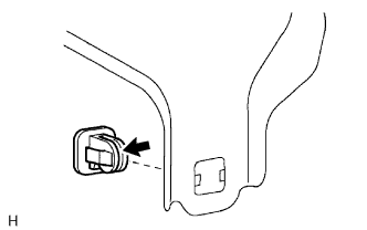
| 1. INSTALL NO. 2 CLUTCH PEDAL CUSHION (w/ Clutch Switch) |
Install the No. 2 clutch pedal cushion to the clutch pedal sub-assembly.
 |
| 2. INSTALL PEDAL SPRING HOOK (w/ Turnover) |
Apply MP grease to the contact surface of the pedal spring hook and install the hook to the clutch pedal support sub-assembly.
Text in Illustration 
MP grease
 |
| 3. INSTALL CLUTCH MASTER CYLINDER PUSH ROD CLEVIS BUSH |
Apply MP grease to the inside of a new clutch master cylinder push rod clevis bush.
Text in Illustration MP grease
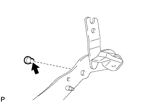 |
Install the clevis bush to the clutch pedal sub-assembly.
- HINT:
- Install the clevis bush from the left side of the vehicle.
| 4. INSTALL NO. 1 CLUTCH PEDAL CUSHION |
Install the No. 1 clutch pedal cushion to the clutch pedal sub-assembly.
 |
| 5. INSTALL CLUTCH PEDAL BUSH |
Apply MP grease to the collar and the inside and outside of 2 new clutch pedal bushes.
Text in Illustration MP grease
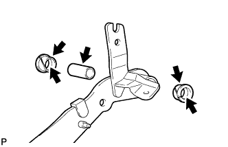 |
Install the 2 bushes and collar to the clutch pedal sub-assembly.
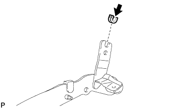
| 6. INSTALL CLUTCH PEDAL TURNOVER BUSH (w/ Turnover) |
Apply MP grease to the inside of the clutch pedal turnover bush and install the bush to the clutch pedal sub-assembly.
Text in Illustration MP grease
 |
| 7. INSTALL CLUTCH PEDAL SPRING HOLDER (w/ Turnover) |
Apply MP grease to the contact surface of the clutch pedal spring holder and install the holder to the clutch pedal support sub-assembly.
Text in Illustration MP grease
 |
| 8. INSTALL CLUTCH PEDAL SUB-ASSEMBLY |
Install the clutch pedal sub-assembly to the clutch pedal support sub-assembly with the bolt and nut.
- Torque:
- 26 N*m{265 kgf*cm, 19 ft.*lbf}
- HINT:
- Install the bolt from the right side of the vehicle.
w/ Turnover:
Apply MP grease to the inside of the hole in the hook and to the sliding areas of the spring, and then install the pedal spring with hook.Text in Illustration MP grease
 |
| 9. INSTALL CLUTCH PEDAL SPRING (w/ Turnover) |
Move the pedal to the full stroke position.
Install the clutch pedal spring to the clutch pedal assembly.
| 10. INSTALL CLUTCH SWITCH ASSEMBLY (w/ Clutch Switch) |
Temporarily install the clutch switch.
Adjust the switch position so that the clearance shown in the illustration between the clutch switch and cushion is within the specified range.
- Standard Clearance:
- 0.6 to 1.0 mm (0.0236 to 0.0394 in.)
- NOTICE:
- Before performing the clutch switch assembly adjustment, adjust the pedal free play (HILUX_TGN26 RM0000010R101RX.html).
 |
Tighten the adjusting nut to the specified torque.
- Torque:
- 16 N*m{160 kgf*cm, 12 ft.*lbf}
| 11. INSTALL CLUTCH PEDAL PAD |
| 12. INSTALL CLUTCH PEDAL ASSEMBLY |
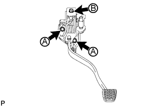 |
Install the clutch pedal with the bolt and 2 nuts.
- Torque:
- for nut A:
- 14 N*m{145 kgf*cm, 10 ft.*lbf}
- for bolt B:
- 18 N*m{184 kgf*cm, 13 ft.*lbf}
w/ Clutch Switch:
Connect the clutch switch connector.
| 13. CONNECT CLUTCH MASTER CYLINDER PUSH ROD CLEVIS |
Apply MP grease to the contact surface of the clevis pin.
Text in Illustration MP grease
 |
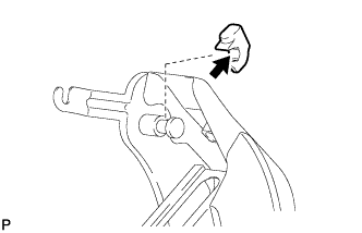
Connect the clutch master cylinder push rod clevis with the clevis pin and install a new clip.
w/o Turnover:
Connect the clutch pedal spring to the clevis pin and clutch pedal support to install it.
| 14. INSPECT AND ADJUST CLUTCH PEDAL ASSEMBLY |
Fold back the floor carpet to expose the asphalt sheet under the pedal.
Check that the pedal height is correct.
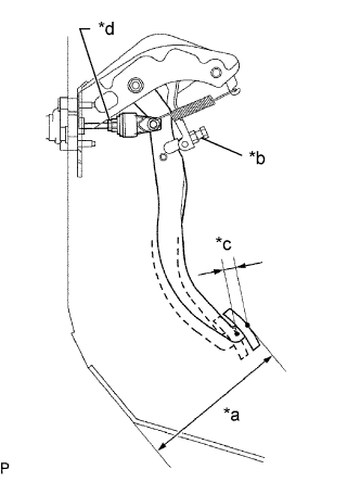
Text in Illustration *a Pedal Height *b Pedal Height Adjustment Point *c Push Rod Play *d Push Rod Play Adjustment Point - Pedal height from dash panel:
- 179.6 to 189.6 mm (7.07 to 7.46 in.)
 |
w/o Clutch Switch:
Adjust the pedal height.Loosen the lock nut of the stopper bolt and turn the stopper bolt until the pedal height is within the specified range.
Tighten the lock nut.
- Torque:
- 25 N*m{255 kgf*cm, 18 ft.*lbf}
w/ Clutch Switch:
Adjust the pedal height.Loosen the lock nut of the stopper bolt and the clutch switch. Then turn the clutch switch backward.
Turn the stopper bolt until the pedal height is within the specified range.
Tighten the lock nut of the stopper bolt.
- Torque:
- 25 N*m{255 kgf*cm, 18 ft.*lbf}
Adjust the clutch switch assembly (HILUX_TGN26 RM000004FUB00UX.html).
Check the pedal free play and push rod play.
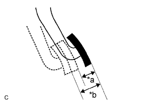
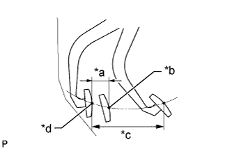
Text in Illustration *a Push Rod Play *b Pedal Free Play Depress the clutch pedal until resistance is felt.
Measure the distance between the position of the pedal when it is released and the position in the previous step.
- Standard pedal free play:
- 5.0 to 15.0 mm (0.197 to 0.591 in.)
Release the pedal. Using your finger, gently press the pedal until resistance increases slightly.
Measure the distance between the position of the pedal when it is released and the position in the previous step.
- Standard push rod play at pedal top:
- 1.0 to 5.0 mm (0.0394 to 0.197 in.)
 |
Adjust the pedal free play and push rod play.
Loosen the lock nut and turn the push rod until the pedal free play and push rod play are within the specified range.
Tighten the lock nut.
- Torque:
- 12 N*m{120 kgf*cm, 9 ft.*lbf}
After adjusting the pedal free play, check the pedal height.
Check the clutch release point.
Text in Illustration *a 25 mm or more *b Release Point *c Pedal Stroke *d Full Stroke End Position Pull the parking brake lever and use wheel chocks to stabilize the vehicle.
Start the engine and run it at idle.
Without depressing the clutch pedal, slowly move the shift lever to R until the gears contact each other.
Gently depress the clutch pedal and measure the stroke distance from the point that the gear noise stops (release point) up to the full stroke end position.
- Standard distance A:
- 25 mm (0.984 in.) or more
- Check pedal height.
- Check push rod play and pedal free play.
- Bleed air from clutch line.
- Check clutch cover and disc.
 |
| 15. INSTALL COMBINATION METER ASSEMBLY |
| 16. CHECK FLUID LEVEL IN RESERVOIR |
Check for brake fluid leaks.
Check the brake fluid level in the reservoir (HILUX_TGN26 RM0000010K400UX_01_0001.html).
Install the brake master cylinder reservoir filler cap assembly.