Automatic Transmission System (For 1Kd-Ftv With I-Art) Ecu Power Source Circuit
Drivetrain. Hilux. Tgn26, 36 Kun25, 26, 35, 36 Ggn25
DESCRIPTION
WIRING DIAGRAM
INSPECTION PROCEDURE
INSPECT IGNITION SWITCH
CHECK HARNESS AND CONNECTOR (TCM - BODY GROUND)
CHECK TCM (TCM - BATTERY)
AUTOMATIC TRANSMISSION SYSTEM (for 1KD-FTV with i-ART) - ECU Power Source Circuit |
DESCRIPTION
When the ignition switch is turned to ON, battery voltage is applied to terminal IG2 of the TCM.
WIRING DIAGRAM
INSPECTION PROCEDURE
- NOTICE:
- Inspect the fuses for circuits related to this system before performing the following inspection procedure.
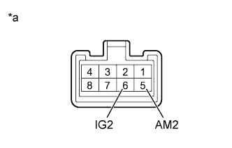
| 1.INSPECT IGNITION SWITCH |
Disconnect the ignition switch connector.
Measure the resistance according to the value(s) in the table below.
- Standard Resistance:
Tester Connection
| Switch Condition
| Specified Condition
|
5 (AM2) - 6 (IG2)
| LOCK
| 10 kΩ or higher
|
5 (AM2) - 6 (IG2)
| ON
| Below 1 Ω
|
Text in Illustration*a
| Component without harness connected
(Ignition Switch)
|
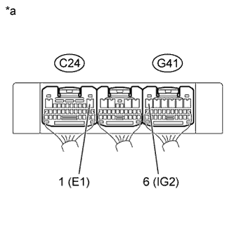
| 2.CHECK HARNESS AND CONNECTOR (TCM - BODY GROUND) |
Disconnect the TCM connector.
Measure the resistance according to the value(s) in the table below.
- Standard Resistance:
Tester Connection
| Condition
| Specified Condition
|
C24-1 (E1) - Body ground
| Always
| Below 1 Ω
|
Text in Illustration*a
| Rear view of wire harness connector
(to TCM)
|
| | REPAIR OR REPLACE HARNESS OR CONNECTOR |
|
|
| 3.CHECK TCM (TCM - BATTERY) |
Turn the ignition switch to ON.
Measure the voltage according to the value(s) in the table below.
- Standard Voltage:
Tester Connection
| Switch Condition
| Specified Condition
|
G41-6 (IG2) - C24-1 (E1)
| Ignition switch ON
| 11 to 14 V
|
Text in Illustration*a
| Rear view of wire harness connector
(to TCM)
|
| | REPAIR OR REPLACE HARNESS OR CONNECTOR |
|
|