CHECK DTC OUTPUT (IN ADDITION TO DTC P0751)
INSPECT SHIFT SOLENOID VALVE S1
INSPECT TRANSMISSION VALVE BODY ASSEMBLY
DTC P0751 Shift Solenoid "A" Performance (Shift Solenoid Valve S1) |
DESCRIPTION
The ECM uses signals from the output shaft speed sensor and input speed sensor to detect the actual gear position (1st, 2nd, 3rd or 4th gear).Then the ECM compares the actual gear with the shift schedule in the ECM memory to detect mechanical problems of the shift solenoid valves, valve body and automatic transmission (clutch, brake, gear, etc.).
| DTC Code | DTC Detection Condition | Trouble Area |
| P0751 | S1 stuck ON malfunction*1: The ECM determines there is a malfunction when the following conditions are both met (2-trip detection logic): (a) When the ECM directs the transmission to switch to 3rd gear, the actual gear is shifted to 2nd. (b) When the ECM directs the transmission to switch to 4th gear, the actual gear is shifted to 1st. |
|
| P0751 | S1 stuck OFF malfunction*2: The ECM determines there is a malfunction when the following conditions are both met (2-trip detection logic): (a) When the ECM directs the transmission to switch to 1st gear, the actual gear is shifted to 4th. (b) When the ECM directs the transmission to switch to 4th gear, the actual gear is shifted to 4th. |
|
- HINT:
- Gear positions in the event of a solenoid valve mechanical problem:
| ECM gear shift command | 1st | 2nd | 3rd | 4th |
| *1: Actual gear position under S1 stuck ON malfunction | 1st | 2nd | 2nd | 1st |
| *2: Actual gear position under S1 stuck OFF malfunction | 4th | 3rd | 3rd | 4th |
MONITOR DESCRIPTION
This DTC indicates a "stuck ON malfunction" or "stuck OFF malfunction" of shift solenoid valve S1.The ECM commands gear shifts by turning the shift solenoid valves ON/OFF. When the gear position commanded by the ECM and the actual gear position are not the same, the ECM illuminates the MIL and stores the DTC.
INSPECTION PROCEDURE
| ACTIVE TEST |
- HINT:
- Using the intelligent tester to perform Active Tests allows relays, VSVs, actuators and other items to be operated without removing any parts. This non-intrusive functional inspection can be very useful because intermittent operation may be discovered before parts or wiring is disturbed. Performing Active Tests early in troubleshooting is one way to save diagnostic time. Data List information can be displayed while performing Active Tests.
Warm up the engine.
Turn the ignition switch off.
Connect the intelligent tester to the DLC3.
Turn the ignition switch to ON.
Turn the intelligent tester on.
Enter the following menus: Powertrain / Engine and ECT / Active Test.
According to the display on the tester, perform the Active Test.
- HINT:
- While driving, the shift position can be forcibly changed with the intelligent tester.
- Comparing the shift position commanded by the Active Test with the actual shift position enables you to confirm the problem (HILUX_TGN26 RM000000O8L0KVX.html).
Engine and ECT Tester Display Test Part Control Range Diagnostic Note Control the Shift Position Operate shift solenoid valves and set each shift position - Press "→" button: Shift up
- Press "←" button: Shift down
Possible to check operation of the shift solenoid valves.
[Vehicle Condition]
50 km/h (30 mph) or less- HINT:
- This test can be conducted when the vehicle speed is 50 km/h (30 mph) or less.
- The 3rd to 4th up-shift must be performed with the accelerator pedal released.
- Do not operate the accelerator pedal for at least 2 seconds after shifting and do not shift successively.
- The shift position commanded by the ECM is shown in the Data List display on the intelligent tester.
- Shift solenoid valve S1 turns ON/OFF normally when the shift lever is in D.
ECM gear shift command 1st 2nd 3rd 4th Shift solenoid valve S1 ON ON OFF OFF
| 1.CHECK DTC OUTPUT (IN ADDITION TO DTC P0751) |
Connect the intelligent tester to the DLC3.
Turn the ignition switch to ON.
Turn the intelligent tester on.
Enter the following menus: Powertrain / Engine and ECT / DTC.
Read the DTCs using the intelligent tester.
Result Result Proceed to Only P0751 is output A P0751 and other DTCs are output B - HINT:
- If any other codes besides P0751 are output, perform troubleshooting for those DTCs first.
|
| ||||
| A | |
| 2.INSPECT SHIFT SOLENOID VALVE S1 |
Remove shift solenoid valve S1.
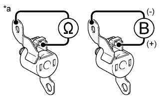 |
Measure the resistance according to the value(s) in the table below.
- Standard Resistance:
Tester Connection Condition Specified Condition Shift solenoid valve S1 connector terminal - Shift solenoid valve S1 body 20°C (68°F) 11 to 15 Ω
Apply 12 V battery voltage to the shift solenoid valve and check that the valve moves and makes an operating noise.
- OK:
Measurement Condition Specified Condition - Battery positive (+) → Shift solenoid valve S1 connector
- Battery negative (-) → Shift solenoid valve S1 body
Valve moves and makes an operating noise - Battery positive (+) → Shift solenoid valve S1 connector
| *a | Component without harness connected (Shift Solenoid Valve S1) |
|
| ||||
| OK | |
| 3.INSPECT TRANSMISSION VALVE BODY ASSEMBLY |
Check the transmission valve body assembly (HILUX_TGN26 RM0000013BC01VX.html).
- OK:
- There are no foreign objects on each valve.
|
| ||||
| OK | ||
| ||