Automatic Transmission System (For 2Tr-Fe) Park / Neutral Position Switch Circuit
Drivetrain. Hilux. Tgn26, 36 Kun25, 26, 35, 36 Ggn25
DESCRIPTION
WIRING DIAGRAM
INSPECTION PROCEDURE
CHECK PARK/NEUTRAL POSITION SWITCH ASSEMBLY (POWER SOURCE)
CHECK HARNESS AND CONNECTOR (NSW TERMINAL VOLTAGE)
INSPECT PARK/NEUTRAL POSITION SWITCH ASSEMBLY
INSPECT SHIFT LOCK CONTROL ECU
CHECK HARNESS AND CONNECTOR (PARK/NEUTRAL POSITION SWITCH - SHIFT LOCK CONTROL ECU)
CHECK HARNESS AND CONNECTOR (PARK/NEUTRAL POSITION SWITCH - ECM)
CHECK HARNESS AND CONNECTOR (PARK/NEUTRAL POSITION SWITCH - ECM)
AUTOMATIC TRANSMISSION SYSTEM (for 2TR-FE) - Park / Neutral Position Switch Circuit |
DESCRIPTION
The Park/Neutral Position (PNP) switch detects the shift lever position and sends signals to the ECM.
WIRING DIAGRAM
INSPECTION PROCEDURE
| 1.CHECK PARK/NEUTRAL POSITION SWITCH ASSEMBLY (POWER SOURCE) |
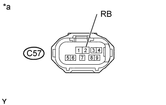
Disconnect the park/neutral position switch connector.
Measure the voltage according to the value(s) in the table below.
- Standard Voltage:
Tester Connection
| Switch Condition
| Specified Condition
|
C57-2 (RB) - Body ground
| Ignition switch ON
| 11 to 14 V
|
C57-2 (RB) - Body ground
| Ignition switch off
| Below 1 V
|
Text in Illustration*a
| Front view of wire harness connector
(to Park/Neutral Position Switch)
|
| | REPAIR OR REPLACE HARNESS OR CONNECTOR |
|
|
| 2.CHECK HARNESS AND CONNECTOR (NSW TERMINAL VOLTAGE) |
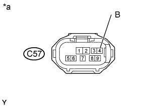
Disconnect the park/neutral position switch connector.
Measure the voltage according to the value(s) in the table below.
- Standard Voltage:
Tester Connection
| Switch Condition
| Specified Condition
|
C57-4 (B) - Body ground
| Ignition switch ON
| 11 to 14 V
|
C57-4 (B) - Body ground
| Ignition switch off
| Below 1 V
|
Text in Illustration*a
| Front view of wire harness connector
(to Park/Neutral Position Switch)
|
| 3.INSPECT PARK/NEUTRAL POSITION SWITCH ASSEMBLY |
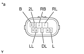
Disconnect the park/neutral position switch connector.
Measure the resistance according to the value(s) in the table below.
- Standard Resistance:
Tester Connection
| Condition
| Specified Condition
|
4 (B) - 5 (L)
| Shift lever in P
| Below 1 Ω
|
2 (RB) - 1 (RL)
| Shift lever in R
| Below 1 Ω
|
4 (B) - 5 (L)
| Shift lever in N
| Below 1 Ω
|
2 (RB) - 7 (DL)
| Shift lever in D or 3
| Below 1 Ω
|
2 (RB) - 3 (2L)
| Shift lever in 2
| Below 1 Ω
|
2 (RB) - 8 (LL)
| Shift lever in L
| Below 1 Ω
|
4 (B) - 5 (L)
| Shift lever not in P
| 10 kΩ or higher
|
2 (RB) - 1 (RL)
| Shift lever not in R
| 10 kΩ or higher
|
4 (B) - 5 (L)
| Shift lever not in N
| 10 kΩ or higher
|
2 (RB) - 7 (DL)
| Shift lever not in D or 3
| 10 kΩ or higher
|
2 (RB) - 3 (2L)
| Shift lever not in 2
| 10 kΩ or higher
|
2 (RB) - 8 (LL)
| Shift lever not in L
| 10 kΩ or higher
|
Text in Illustration*a
| Component without harness connected
(Park/Neutral Position Switch)
|
| 4.INSPECT SHIFT LOCK CONTROL ECU |
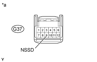
Disconnect the shift lock control ECU connector.
Measure the resistance according to the value(s) in the table below.
- Standard Resistance:
Tester Connection
| Condition
| Specified Condition
|
3 (AT3) - 9 (NSSD)
| Shift lever in 3
| Below 1 Ω
|
3 (AT3) - 9 (NSSD)
| Shift lever in D
| 10 kΩ or higher
|
Text in Illustration*a
| Component without harness connected
(Shift Lock Control ECU)
|
| 5.CHECK HARNESS AND CONNECTOR (PARK/NEUTRAL POSITION SWITCH - SHIFT LOCK CONTROL ECU) |
Disconnect the shift lock control ECU connector.
Measure the voltage according to the value(s) in the table below.
- Standard Voltage:
Tester Connection
| Condition
| Specified Condition
|
G37-9 (NSSD) - Body ground
| - Ignition switch ON
- Shift lever in D or 3
| 11 to 14 V
|
G37-9 (NSSD) - Body ground
| - Ignition switch ON
- Shift lever not in D or 3
| Below 1 V
|
Text in Illustration*a
| Front view of wire harness connector
(to Shift Lock Control ECU)
|
| | REPAIR OR REPLACE HARNESS OR CONNECTOR |
|
|
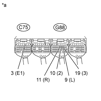
| 6.CHECK HARNESS AND CONNECTOR (PARK/NEUTRAL POSITION SWITCH - ECM) |
Measure the voltage according to the value(s) in the table below.
- Standard Voltage:
Tester Connection
| Condition
| Specified Condition
|
G88-11 (R) - C75-3 (E1)
| - Ignition switch ON
- Shift lever in R
| 11 to 14 V*
|
G88-19 (3) - C75-3 (E1)
| - Ignition switch ON
- Shift lever in 3
| 11 to 14 V
|
G88-10 (2) - C75-3 (E1)
| - Ignition switch ON
- Shift lever in 2
| 11 to 14 V
|
G88-9 (L) - C75-3 (E1)
| - Ignition switch ON
- Shift lever in L
| 11 to 14 V
|
G88-11 (R) - C75-3 (E1)
| - Ignition switch ON
- Shift lever not in R
| Below 1 V
|
G88-19 (3) - C75-3 (E1)
| - Ignition switch ON
- Shift lever not in 3
| Below 1 V
|
G88-10 (2) - C75-3 (E1)
| - Ignition switch ON
- Shift lever not in 2
| Below 1 V
|
G88-9 (L) - C75-3 (E1)
| - Ignition switch ON
- Shift lever not in L
| Below 1 V
|
Text in Illustration*a
| Rear view of wire harness connector
(to ECM)
|
- HINT:
- *: The voltage will drop slightly due to the illumination of the back-up light.
| | REPAIR OR REPLACE HARNESS OR CONNECTOR |
|
|
| 7.CHECK HARNESS AND CONNECTOR (PARK/NEUTRAL POSITION SWITCH - ECM) |
Disconnect the C57 park/neutral position switch connector.
Disconnect the G89 ECM connector.
Measure the resistance according to the value(s) in the table below.
- Standard Resistance:
Tester Connection
| Condition
| Specified Condition
|
C57-4 (B) - G89-30 (NSW)
| Always
| Below 1 Ω
|
C57-4 (B) - Body ground
| Always
| 10 kΩ or higher
|
| | REPAIR OR REPLACE HARNESS OR CONNECTOR |
|
|