Dtc P0571 Stop Light Switch Circuit Malfunction
DESCRIPTION
WIRING DIAGRAM
INSPECTION PROCEDURE
READ VALUE USING INTELLIGENT TESTER (STOP LIGHT SWITCH)
CHECK HARNESS AND CONNECTOR (BATTERY - STOP LIGHT SWITCH)
INSPECT STOP LIGHT SWITCH ASSEMBLY
CHECK HARNESS AND CONNECTOR (STOP LIGHT SWITCH - ECM)
DTC P0571 Stop Light Switch Circuit Malfunction |
DESCRIPTION
When the brake pedal is depressed, the stop light switch sends a signal to the ECM. Upon receiving the signal, the ECM cancels cruise control. Even if there is a malfunction in the stop light signal circuit while cruise control is in operation, normal driving is maintained due to a fail-safe function. When the brake pedal is depressed, positive voltage is applied to terminal STP of the ECM through the STOP fuse and stop light switch, and the ECM cancels cruise control.DTC Code
| DTC Detection Condition
| Trouble Area
|
P0571
| The voltages of terminals ST1- and STP of the ECM are both below 1 V for 0.5 seconds or more.
| - Stop light switch circuit
- Stop light switch assembly
- ECM
|
WIRING DIAGRAM
INSPECTION PROCEDURE
- NOTICE:
- Inspect the fuses for circuits related to this system before performing the following inspection procedure.
| 1.READ VALUE USING INTELLIGENT TESTER (STOP LIGHT SWITCH) |
Using the intelligent tester, read the Data List (HILUX_TGN26 RM000000PM306GX.html).
Cruise ControlTester Display
| Measurement Item/Range
| Normal Condition
| Diagnostic Note
|
Stop Light SW M-CPU
| Stop light switch signal (Main CPU) / ON or OFF
| ON: Brake pedal depressed
OFF: Brake pedal released
| -
|
- OK:
- The display is as specified in the normal condition column.
| 2.CHECK HARNESS AND CONNECTOR (BATTERY - STOP LIGHT SWITCH) |
Disconnect the A24 stop light switch connector.
Measure the voltage according to the value(s) in the table below.
- Standard Voltage:
Tester Connection
| Condition
| Specified Condition
|
A24-2 - Body ground
| Always
| 11 to 14 V
|
A24-3 - Body ground
| Ignition switch ON
| 11 to 14 V
|
Ignition switch off
| Below 1 V
|
| | REPAIR OR REPLACE HARNESS OR CONNECTOR |
|
|
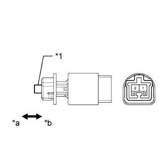
| 3.INSPECT STOP LIGHT SWITCH ASSEMBLY |
Remove the stop light switch (HILUX_TGN26 RM0000018VF00UX.html).
Measure the resistance according to the value(s) in the table below.
- Standard Resistance:
Tester Connection
| Switch Condition
| Specified Condition
|
1 - 2
| Pin pushed
| 10 kΩ or higher
|
Pin not pushed
| Below 1 Ω
|
3 - 4
| Pin pushed
| Below 1 Ω
|
Pin not pushed
| 10 kΩ or higher
|
Text in Illustration*1
| Pin
|
*a
| Not pushed
|
*b
| Pushed
|
| 4.CHECK HARNESS AND CONNECTOR (STOP LIGHT SWITCH - ECM) |
Disconnect the A24 stop light switch connector.
Disconnect the G38 ECM connector.
Measure the resistance according to the value(s) in the table below.
- Standard Resistance:
Tester Connection
| Condition
| Specified Condition
|
A24-1 - G38-15 (STP)
| Always
| Below 1 Ω
|
A24-4 - G38-14 (ST1-)
|
A24-1 - Body ground
| Always
| 10 kΩ or higher
|
A24-4 - Body ground
|
| | REPAIR OR REPLACE HARNESS OR CONNECTOR |
|
|