Exhaust Manifold W/ Turbocharger (W/ Egr Cooler) -- Installation |
| 1. INSTALL EXHAUST MANIFOLD |
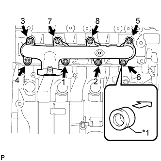
Install a new gasket, exhaust manifold, 8 new collars and 8 plate washers to the cylinder head with 8 new nuts.
- Torque:
- 40 N*m{408 kgf*cm, 30 ft.*lbf}
Text in Illustration *1 Collar 
Engine Side - NOTICE:
- Make sure that the side of the collar with the smaller diameter faces the exhaust manifold.
- Tighten the nuts in the order shown in the illustration.
 |
| 2. CLEAN TURBOCHARGER SUB-ASSEMBLY |
| 3. INSTALL TURBOCHARGER SUB-ASSEMBLY |
Temporarily install a new gasket and the turbocharger with 3 new nuts.
- HINT:
- It is easier to install the turbo oil inlet pipe if the 3 nuts are only loosely installed.
Temporarily install the turbo oil inlet pipe.
Text in Illustration *1 New Gasket *2 Claw *3 Narrow *4 Wide 
Outside Install a new gasket and the oil inlet pipe with the 2 nuts, but only loosely install the nuts.
- NOTICE:
- The notch (wide part) of the gasket must face the engine.
Install a new gasket and the oil inlet pipe with the 2 bolts, but only loosely install the bolts.
- NOTICE:
- The claws of the gasket must face the pipe.
Install a new gasket and the oil inlet pipe with the union bolt, but only loosely install the union bolt.
Temporarily install the turbocharger stay with the 2 bolts and nut.
 |
Tighten the 3 nuts of the turbocharger.
- Torque:
- 52 N*m{530 kgf*cm, 38 ft.*lbf}
Tighten the 2 nuts and 2 bolts of the turbo oil inlet pipe, and the union bolt.
- Torque:
- for bolt:
- 12 N*m{122 kgf*cm, 9 ft.*lbf}
- for nut:
- 13 N*m{133 kgf*cm, 10 ft.*lbf}
- for union bolt:
- 26 N*m{265 kgf*cm, 19 ft.*lbf}
Tighten the 2 bolts and nut of the turbocharger stay.
- Torque:
- 38 N*m{387 kgf*cm, 28 ft.*lbf}
| 4. INSTALL TURBINE OUTLET ELBOW |
Install a new gasket and the turbine outlet elbow with the 4 new nuts.
- Torque:
- 26 N*m{260 kgf*cm, 19 ft.*lbf}
| 5. INSTALL NO. 1 EXHAUST MANIFOLD HEAT INSULATOR |
Install the No. 1 exhaust manifold heat insulator with the 2 bolts.
- Torque:
- 12 N*m{122 kgf*cm, 9 ft.*lbf}
| 6. INSTALL COMPRESSOR INLET ELBOW |
Install the air cleaner hose and air No. 3 cleaner hose with the clamp labeled A as shown in the illustration.
- HINT:
- Align the protrusion of the turbocharger and the protrusion of the hose.
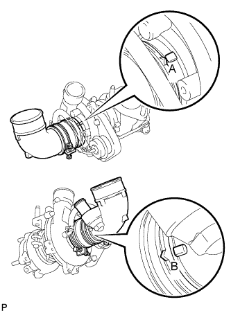 |
Install the compressor inlet elbow with the clamp labeled B as shown in the illustration.
- HINT:
- Install the inlet elbow with the clamp labeled B as shown in the illustration.
| 7. INSTALL VENTILATION PIPE |
Connect the 2 ventilation hoses to the cylinder head cover and compressor inlet elbow.
Install the ventilation pipe to the cylinder head with the bolt.
- Torque:
- 20 N*m{204 kgf*cm, 15 ft.*lbf}
| 8. INSTALL AIR CLEANER ASSEMBLY |
Connect the No. 1 air cleaner hose.
Install the cleaner with the 2 bolts.
- Torque:
- 14 N*m{143 kgf*cm, 10 ft.*lbf}
Connect the connector to the mass air flow meter.
Tighten the hose clamp.
| 9. INSTALL INTERCOOLER ASSEMBLY |
| 10. INSTALL FRONT EXHAUST PIPE ASSEMBLY |
Using a vernier caliper, measure the free length of the compression spring.
- Minimum length:
- 40 mm (1.57 in.)
 |
Install the front exhaust pipe to the exhaust pipe support.
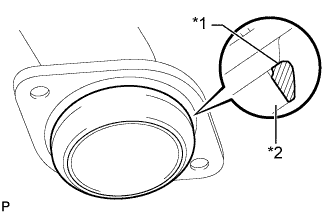
Install a new gasket to the turbine outlet elbow.
Text in Illustration *1 Gasket *2 Turbine Outlet Elbow - NOTICE:
- Be careful with the installation direction of the gasket.
- Do not reuse the gasket.
- To ensure a proper seal, do not use the front exhaust pipe to force the gasket onto the turbine outlet elbow.
- HINT:
- Using a plastic-faced hammer, uniformly strike the gasket so that the gasket and turbine outlet elbow are properly fit.
 |
Install the front exhaust pipe and 2 compression springs with the 2 bolts. Alternately tighten the bolts in several passes.
- Torque:
- 43 N*m{438 kgf*cm, 32 ft.*lbf}
| 11. CONNECT CABLE TO NEGATIVE BATTERY TERMINAL |
- NOTICE:
- When disconnecting the cable, some systems need to be initialized after the cable is reconnected (HILUX_TGN26 RM000004QR3003X.html).
| 12. INSPECT FOR OIL LEAK |
Start the engine. Make sure that there are no oil leaks from the areas that were worked on.
| 13. INSPECT FOR EXHAUST LEAK |
| 14. INSTALL FRONT FENDER APRON SEAL UPPER |
Install the front fender apron seal upper with the 5 clips.
| 15. INSTALL FRONT FENDER SEAL |
Install the front fender seal with the 5 clips.
| 16. INSTALL FRONT WHEEL RH |
| 17. INSTALL NO. 2 ENGINE UNDER COVER |
- Torque:
- 28 N*m{286 kgf*cm, 21 ft.*lbf}
| 18. INSTALL NO. 1 ENGINE UNDER COVER |
- Torque:
- 28 N*m{286 kgf*cm, 21 ft.*lbf}