Fuel Sub Tank -- Installation |
| 1. INSTALL BREATHER TUBE FUEL HOSE |
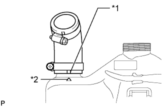
Align the paint mark and protrusion as shown in the illustration and install the breather tube fuel hose, and then tighten the hose clamp in the position shown in the illustration.
Text in Illustration *1 Paint Mark (Yellow) *2 Protrusion
 |
| 2. INSTALL FUEL TANK FILLER PIPE |
Align the protrusion and paint mark as shown in the illustration and install the fuel tank filler pipe, and then tighten the hose clamp in the position shown in the illustration.
Text in Illustration *1 Paint Mark (Blue) *2 Protrusion
 |
| 3. INSTALL FUEL SUCTION PLATE SUB-ASSEMBLY |
Install a new fuel suction tube set gasket.
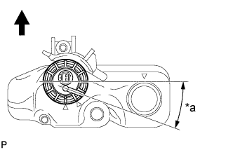
Set the fuel suction plate sub-assembly to the auxiliary fuel tank shown in the illustration.
Text in Illustration *a 5° to 15° 
Front Side
 |
While holding the fuel suction plate sub-assembly by hand to prevent it from tilting, align the mark on the new fuel pump gauge retainer with the start mark on the auxiliary fuel tank and tighten the fuel pump gauge retainer 720° by hand.
Text in Illustration *1 Start Mark *2 Mark Front Side - NOTICE:
- Perform this work by hand. Do not use any tools.
 |
| 4. INSTALL CHECK VALVE GASKET |
Apply a light coat of gasoline to a new check valve gasket, then install it.
| 5. INSTALL FUEL PUMP |
Insert the fuel pump.
| 6. INSTALL NO. 2 FUEL TUBE SUB-ASSEMBLY |
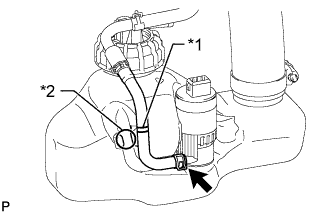
Connect the No. 2 fuel tube sub-assembly, then attach the claw.
Text in Illustration *1 Mark *2 Clamp - NOTICE:
- Install the marked parts of the No. 2 fuel tube sub-assembly to the clamp.
 |
Connect the fuel pump connector.
| 7. INSTALL FUEL TANK CAP COVER |
Install the fuel tank cap cover with a new tie wrap.
| 8. INSTALL FUEL TANK CAP ASSEMBLY |
| 9. INSTALL FUEL TANK FILLER PIPE SUPPORT |
Install the No. 1 fuel tank filler pipe support and No. 2 fuel tank filler pipe support as shown in the illustration.
 |
| 10. INSTALL SOLENOID VALVE ASSEMBLY |
Install the solenoid valve assembly with the bolt.
- Torque:
- 7.0 N*m{71 kgf*cm, 62 in.*lbf}
Connect the hose.
| 11. INSTALL AUXILIARY FUEL TANK ASSEMBLY |
Install the auxiliary fuel tank assembly with the 2 bolts.
- Torque:
- 12 N*m{122 kgf*cm, 9 ft.*lbf}
- NOTICE:
- Do not drop the auxiliary fuel tank.
- Do not damage the piping or wiring.
Connect the No. 2 fuel tank filler tube.
Connect the fuel pump connector.
Connect the No. 4 fuel hose.
Connect the fuel sender gauge connector.
Connect the connector and No. 3 fuel hose.
| 12. ADD FUEL |
| 13. CONNECT CABLE TO NEGATIVE BATTERY TERMINAL |
- NOTICE:
- When disconnecting the cable, some systems need to be initialized after the cable is reconnected (HILUX_TGN26 RM000004QR300CX.html).
| 14. INSPECT FOR FUEL LEAK (for Fuel Sub Tank) |
Start the engine.
- NOTICE:
- Perform the inspection while the engine is cold.
- The fuel pump operates only for a calculated time when the coolant temperature is 20°C (68°F) or less and learned ethanol concentration is 85% or more.
Check for fuel leaks.
Check that there are no fuel leaks from the fuel system after doing any maintenance or repairs. If there is a fuel leak, repair or replace parts as necessary.