Camshaft -- Installation |
| 1. INSTALL CAMSHAFT TIMING GEAR ASSEMBLY |
Align the pin hole and straight pin and install the camshaft timing gear to the camshaft.
Text in Illustration *1 Straight Pin *2 Pin Hole
 |
Lightly press the gear against the camshaft and turn the gear. Push further at the position where the pin enters the groove.
- HINT:
- Make sure that there is no gap between the flange of the gear and the camshaft.
With the camshaft timing gear fixed in place, install the flange bolt.
- Torque:
- 78 N*m{795 kgf*cm, 58 ft.*lbf}
Check that the camshaft timing gear can move in the retard direction and becomes locked at the most retarded position.
| 2. INSTALL VALVE LASH ADJUSTER ASSEMBLY |
Inspect each valve lash adjuster before installing it (HILUX_TGN26 RM00000447K00MX_01_0017.html).
Install the 16 valve lash adjusters to the cylinder head.
- NOTICE:
- Install each lash adjuster to the same place it was removed from.
| 3. INSTALL NO. 1 VALVE ROCKER ARM SUB-ASSEMBLY |
Apply clean engine oil to the valve lash adjuster tips and valve stem cap surfaces.
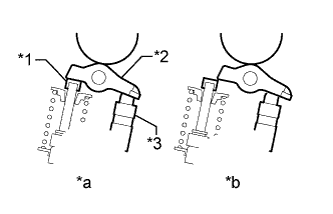
Install the 16 valve rocker arms as shown in the illustration.
Text in Illustration *1 Valve Stem Cap *2 Valve Rocker Arm *3 Valve Lash Adjuster *a CORRECT *b INCORRECT - NOTICE:
- Install the valve stem cap, lash adjuster and valve rocker arm to the same places they were removed from.
 |
| 4. INSTALL CAMSHAFT |
Apply clean engine oil to the camshaft cams and cylinder head journals.
 |
Install the timing chain to the camshaft timing gear with the paint mark of the link aligned with the timing mark of the camshaft timing gear.
Text in Illustration *1 Paint Mark *2 Timing Mark
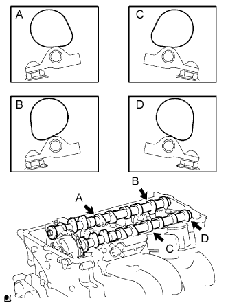
Position the 2 camshafts as shown in the illustration.
- NOTICE:
- Align the paint mark and timing mark before positioning the camshaft.
Before and after positioning the No. 1 camshaft and No. 2 camshaft, check that the rocker arm is firmly set on the lash adjuster.
Text in Illustration *1 Valve Stem Cap *2 Valve Rocker Arm *3 Valve Lash Adjuster *a CORRECT *b INCORRECT
 |
Temporarily install the No. 1 camshaft bearing cap.
 |
Confirm the location for each camshaft bearing cap and install each one to the proper location.
Install a new O-ring to the No. 1 camshaft bearing cap.
Text in Illustration *1 New O-Ring
 |
Temporarily install the oil delivery pipe.
Install the 21 bolts and tighten them in the order shown in the illustration.
- Torque:
- for bolt A:
- 12 N*m{122 kgf*cm, 9 ft.*lbf}
- except bolt A:
- 16 N*m{158 kgf*cm, 11 ft.*lbf}
 |
| 5. INSTALL CAMSHAFT TIMING SPROCKET |
Rotate the camshaft so that the camshaft timing mark and No. 2 camshaft knock pin are as shown in the illustration.
Text in Illustration *1 Timing Mark *2 Knock Pin *3 Groove
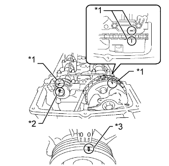 |
Turn the crankshaft pulley and align its groove with the "0" timing mark of the timing chain cover.
Install the timing chain to the camshaft timing sprocket with the paint mark aligned with the timing marks on the camshaft timing sprocket.
Text in Illustration *1 Paint Mark *2 Timing Mark
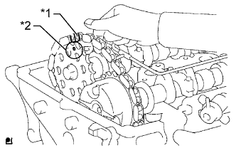 |
Align the No. 2 camshaft knock pin and camshaft timing sprocket pin hole. Then install the camshaft timing sprocket to the No. 2 camshaft.
- NOTICE:
- If the knock pin and pin hole are difficult to align, slightly rotate the No. 2 camshaft back and forth using the hexagonal part of the camshaft. Then attempt alignment again.
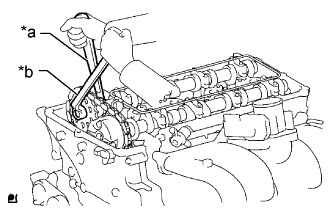
Hold the camshaft with a wrench and tighten the sprocket bolt.
- Torque:
- 78 N*m{795 kgf*cm, 58 ft.*lbf}
Text in Illustration *a Hold *b Tighten
 |
Remove the hexagon wrench from the chain tensioner.
Apply adhesive to 2 or 3 threads of the timing chain cover plug.
- Adhesive:
- Toyota Genuine Adhesive 1324, Three Bond 1324 or equivalent
- NOTICE:
- Remove any oil from the bolt hole.
Using a 10 mm socket hexagon wrench, install the timing chain cover plug.
- Torque:
- 17 N*m{169 kgf*cm, 12 ft.*lbf}
| 6. INSTALL TIMING CHAIN GUIDE |
Install a new O-ring to the camshaft bearing cap.
Text in Illustration *1 New O-Ring
 |
Install the timing chain guide with the 2 bolts.
- Torque:
- 10 N*m{102 kgf*cm, 7 ft.*lbf}
| 7. INSTALL CYLINDER HEAD COVER SUB-ASSEMBLY |
Install 2 new cover gaskets to the head cover.
Apply seal packing to the places shown in the illustration.
- Seal packing:
- Toyota Genuine Seal Packing Black, Three Bond 1207B or equivalent
- Seal packing diameter:
- 4.0 mm (0.157 in.)
Text in Illustration 
Seal Packing - NOTICE:
- Remove any oil from the contact surface.
- Install the head cover within 3 minutes after applying seal packing.
- Do not start the engine for at least 4 hours after the installation.
 |
Temporarily install the cylinder head cover with the 19 bolts and 2 nuts.
Uniformly tighten the 19 bolts and 2 nuts in the order shown in the illustration.
- Torque:
- 9.0 N*m{92 kgf*cm, 80 in.*lbf}
 |
In numerical order, confirm that the bolts labeled 1 to 8 are tightened to the specified torque. Tighten the bolts as necessary.
| 8. INSTALL IGNITION COIL ASSEMBLY |
Install the 4 ignition coils with the 4 bolts.
- Torque:
- 9.0 N*m{92 kgf*cm, 80 in.*lbf}
Connect the ignition coil connector.
| 9. INSTALL INTAKE AIR CONNECTOR |
Install the intake air connector with the 2 bolts, and tighten the 2 hose clamps.
- Torque:
- for intake air connector:
- 8.0 N*m{82 kgf*cm, 71 in.*lbf}
- for hose clamp throttle body side:
- 5.0 N*m{51 kgf*cm, 44 in.*lbf}
- for hose clamp air cleaner side:
- 4.0 N*m{41 kgf*cm, 35 in.*lbf}
Connect the vacuum hose.
Connect the No. 2 ventilation hose.
| 10. INSTALL FAN AND GENERATOR V BELT |
Install the fan and generator V belt to all the pulleys except the V-ribbed belt tensioner pulley.
Text in Illustration *A w/ Air Conditioning System *B w/o Air Conditioning System *1 Generator *2 Idler Pulley *3 Vane Pump *4 Fan Pulley *5 Tensioner Pulley *6 Crankshaft Pulley *7 No. 1 Idler Pulley *8 Cooler Compressor
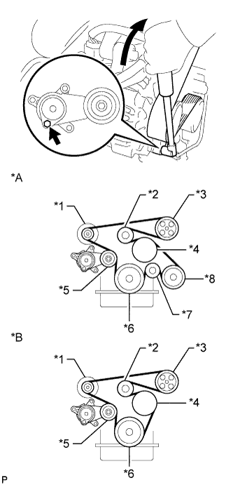 |
Use the hexagon-shaped part indicated by the arrow in the illustration to move the tensioner pulley downward, and then install the fan and generator V belt to the tensioner pulley.
- NOTICE:
- The backside of the fan and generator V belt should face the tensioner pulley.
- Check that the fan and generator V belt is properly installed to each pulley.
| 11. CONNECT CABLE TO NEGATIVE BATTERY TERMINAL |
- NOTICE:
- When disconnecting the cable, some systems need to be initialized after the cable is reconnected (HILUX_TGN26 RM000004QR3009X.html).
| 12. INSPECT FOR OIL LEAK |
Start the engine, and check that there are no oil leaks after performing maintenance.
| 13. INSPECT FOR COOLANT LEAK |
- CAUTION:
- Do not remove the radiator cap while the engine and radiator are still hot. Pressurized, hot engine coolant and steam may be released and cause serious burns.
Fill the radiator with coolant and attach a radiator cap tester.
Warm up the engine.
Using a radiator cap tester, increase the pressure inside the radiator to 118 kPa (1.2 kgf/cm2, 17 psi), and check that the pressure does not drop.
If the pressure drops, check the hoses, radiator and water pump for leaks. If no external leaks are found, check the cylinder block and cylinder head.
| 14. INSPECT IGNITION TIMING |
Warm up and stop the engine.
When using the intelligent tester:
Connect the intelligent tester to the DLC3.
- NOTICE:
- Switch off all the accessories and the A/C before connecting the intelligent tester.
Start the engine and idle it.
Turn the intelligent tester main switch on.
Enter the following menus: Powertrain / Engine and ECT / Data List / IGN Advance.
- Standard ignition timing:
- 0 to 20° BTDC @ idle
- NOTICE:
- When checking the ignition timing, the transmission should be in neutral or park.
- HINT:
- Refer to the intelligent tester operator's manual for further details.
Check that the ignition timing advances immediately when the engine speed is increased.
Enter the following menus: Powertrain / Engine and ECT / Active Test / Connect the TC and TE1.
Monitor IGN Advance.
Perform the Active Test.
- Standard ignition timing:
- 3 to 7° BTDC @ idle
- NOTICE:
- When checking the ignition timing, the transmission should be in neutral or park.
- HINT:
- Refer to the intelligent tester operator's manual for further details.
When not using the intelligent tester:
Using SST, connect a tachometer probe to terminal 9 (TAC) of the DLC3.
- SST
- 09843-18030
Text in Illustration *a Front view of DLC3 - NOTICE:
- Confirm the terminal number before connecting the probe. Connecting the wrong terminals can damage the engine.
- Turn off all electrical systems before connecting the probe.
Connect the tester probe of a timing light to the wire of the ignition coil connector for the No. 1 cylinder.
Start the engine and idle it.
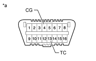
Using SST, connect terminals 13 (TC) and 4 (CG) of the DLC3.
- SST
- 09843-18040
Text in Illustration *a Front view of DLC3 - NOTICE:
- When checking the ignition timing, the transmission should be in neutral.
- HINT:
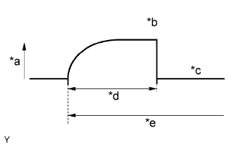
- After connecting terminals TC and CG, the engine speed changes to between approximately 1000 and 1500 rpm for 5 seconds, and then returns to idle as the ECM checks that the ISC (Idle Speed Control) system operates properly.
- Inspect the ignition timing after the engine speed returns to idle.
Text in Illustration *a Engine Speed *b Approx. 1000 to 1500 rpm *c Idle Speed *d 5 sec. *e Connect Terminals TC and CG Using the timing light, measure the ignition timing.
- Standard ignition timing:
- 3 to 7° BTDC @ idle
- NOTICE:
- Turn all the electrical systems and the A/C off.
- When checking the ignition timing, the transmission should be in neutral or park.
Remove SST from the DLC3.
Check the ignition timing.
- Standard ignition timing:
- 0 to 20° BTDC @ idle
Confirm that the ignition timing advances immediately when the engine speed is increased.
Turn the ignition switch off.
Disconnect the timing light from the engine.

| 15. INSPECT ENGINE IDLE SPEED |
Warm up and stop the engine.
When using the intelligent tester:
Connect the intelligent tester to the DLC3.
- NOTICE:
- Switch off all accessories and the air conditioning before connecting the intelligent tester.
Start the engine and idle it.
Turn the intelligent tester on.
Enter the following menus: Powertrain / Engine and ECT / Data List / Engine SPD.
- Standard idle speed:
- 600 to 700 rpm
- NOTICE:
- When checking the idle speed, the transmission should be in neutral.
- HINT:
- Refer to the intelligent tester operator's manual for further details.
Turn the ignition switch off.
Disconnect the intelligent tester from the DLC3.
When not using the intelligent tester:
Using SST, connect a tachometer tester probe to terminal 9 (TAC) of the DLC3.
- SST
- 09843-18030
Text in Illustration *a Front view of DLC3 Start the engine and idle it.
Check the idle speed.
- Standard idle speed:
- 600 to 700 rpm
| 16. CHECK CO/HC |
Start and warm up the engine.
Run the engine at 2500 rpm for approximately 180 seconds, and then idle the engine.
Insert a CO/HC meter testing probe at least 40 cm (1.31 ft.) into the tailpipe.
Check the CO/HC concentration at idle.
- Standard idle CO concentration:
- 0 to 0.5%
- Standard idle HC concentration:
- Refer to applicable local regulation
If the CO/HC concentration is not as specified, perform troubleshooting in the order given below.
Check the air fuel ratio sensor (HILUX_TGN26 RM000001421010X.html) and heated oxygen sensor operation (HILUX_TGN26 RM00000159K00JX.html).
See the table below for possible causes, and then inspect and repair the applicable causes if necessary.
CO HC Problems Causes Normal High Rough idle - Faulty ignition:
- Incorrect timing
- Fouled, shorted or improperly gapped plugs
- Incorrect valve clearance
- Leaks in intake and exhaust valves
- Leaks in cylinders
Low High Rough idle
(Fluctuating HC reading)- Vacuum leaks:
- PCV hoses
- Intake manifold
- Throttle body
- Brake booster line
- Lean mixture causing misfire
High High Rough idle
(Black smoke from exhaust)- Restricted air cleaner filter element
- Plugged PCV valve
- Faulty SFI system:
- Faulty pressure regulator
- Defective engine coolant temperature sensor
- Defective mass air flow meter
- Faulty ECM
- Faulty injectors
- Faulty throttle position sensor
- Faulty ignition: