Cylinder Head Gasket (W/ Dpf) Removal
PRECAUTION
DISCONNECT CABLE FROM NEGATIVE BATTERY TERMINAL
REMOVE NO. 1 ENGINE UNDER COVER
DRAIN ENGINE COOLANT
DRAIN ENGINE OIL
REMOVE INTAKE MANIFOLD
REMOVE GLOW PLUG ASSEMBLY
REMOVE INJECTOR ASSEMBLY
REMOVE COMMON RAIL ASSEMBLY
REMOVE TURBOCHARGER SUB-ASSEMBLY
REMOVE FAN SHROUD
DISCONNECT COOLER COMPRESSOR ASSEMBLY (w/ Air Conditioning System)
REMOVE NO. 1 COMPRESSOR MOUNTING BRACKET (w/ Air Conditioning System)
REMOVE EXHAUST MANIFOLD
REMOVE TIMING BELT
REMOVE CAMSHAFT TIMING PULLEY
REMOVE NO. 2 TIMING BELT COVER
REMOVE CYLINDER BLOCK INSULATOR
REMOVE CAMSHAFT
REMOVE VALVE LIFTER
REMOVE CYLINDER HEAD SUB-ASSEMBLY
REMOVE CYLINDER HEAD GASKET
Cylinder Head Gasket (W/ Dpf) -- Removal |
- NOTICE:
- When replacing the injectors (including shuffling the injectors between the cylinders), common rail or cylinder head, it is necessary to replace the injection pipes with new ones.
- When replacing the fuel supply pump, common rail, cylinder block, cylinder head, cylinder head gasket or timing gear case, it is necessary to replace the fuel inlet pipe with a new one.
- After removing the injection pipes, clean them with a brush and compressed air.
- NOTICE:
- After turning the ignition switch off, waiting time may be required before disconnecting the cable from the battery terminal. Therefore, make sure to read the disconnecting the cable from the battery terminal notice before proceeding with work (HILUX_TGN26 RM000004QR1006X.html).
| 2. DISCONNECT CABLE FROM NEGATIVE BATTERY TERMINAL |
- NOTICE:
- When disconnecting the cable, some systems need to be initialized after the cable is reconnected (HILUX_TGN26 RM000004QR3009X.html).
| 3. REMOVE NO. 1 ENGINE UNDER COVER |
- CAUTION:
- Do not remove the radiator reservoir cap while the engine and radiator are still hot. Pressurized, hot engine coolant and steam may be released and cause serious burns.
Loosen the radiator drain cock plug.
- HINT:
- Collect the coolant in a container and dispose of it according to the regulations in your area.
Drain the coolant by removing the radiator reservoir cap and, using a wrench, remove the vent plug.
Loosen the cylinder block drain cock plug.
Text in Illustration*1
| Radiator Reservoir
| *2
| Radiator Reservoir Cap
|
*3
| Vent Plug
| *4
| Cylinder Block Drain Cock Plug
|
*5
| Radiator Drain Cock Plug
| -
| -
|
Remove the oil filler cap.
Remove the oil pan drain plug and gasket, and then drain the engine oil into a container.
Wipe the oil pan and drain plug.
Install a new gasket and the oil pan drain plug.
- Torque:
- 34 N*m{347 kgf*cm, 25 ft.*lbf}
| 6. REMOVE INTAKE MANIFOLD |
(HILUX_TGN26 RM0000044GF00HX.html)
| 7. REMOVE GLOW PLUG ASSEMBLY |
(HILUX_TGN26 RM000000JIT00KX.html)
| 8. REMOVE INJECTOR ASSEMBLY |
(HILUX_TGN26 RM0000044TN00GX.html)
| 9. REMOVE COMMON RAIL ASSEMBLY |
(HILUX_TGN26 RM0000044W300GX.html)
| 10. REMOVE TURBOCHARGER SUB-ASSEMBLY |
(HILUX_TGN26 RM000002S6F00IX.html)
(HILUX_TGN26 RM000001448022X.html)
| 12. DISCONNECT COOLER COMPRESSOR ASSEMBLY (w/ Air Conditioning System) |
Remove the 4 bolts and disconnect the cooler compressor.
- HINT:
- It is not necessary to completely remove the cooler compressor. With the hoses connected to the cooler compressor, hang the cooler compressor on the vehicle body with a rope.
| 13. REMOVE NO. 1 COMPRESSOR MOUNTING BRACKET (w/ Air Conditioning System) |
Remove the 4 bolts and No. 1 compressor mounting bracket.
| 14. REMOVE EXHAUST MANIFOLD |
Remove the 8 nuts, 8 plate washers, 8 collars and exhaust manifold.
Remove the gasket.
(HILUX_TGN26 RM00000147C01NX.html)
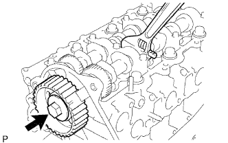
| 16. REMOVE CAMSHAFT TIMING PULLEY |
Remove the bolt of the camshaft timing pulley while holding the camshaft with a wrench.
- NOTICE:
- Make sure the timing belt is not installed when removing the bolt of the camshaft timing pulley.
Remove the camshaft timing pulley.
| 17. REMOVE NO. 2 TIMING BELT COVER |
Remove the 4 bolts, nut and No. 2 timing belt cover.
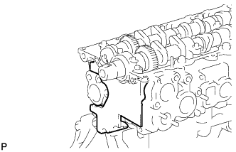
| 18. REMOVE CYLINDER BLOCK INSULATOR |
Remove the cylinder block insulator from the cylinder head.
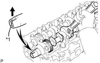
Turn the camshaft with a wrench so that the key groove of the camshaft faces upward.
Text in Illustration*1
| Key Groove
|
Uniformly loosen the 15 bearing cap bolts in several passes in the sequence shown in the illustration.
Remove the 15 bearing cap bolts, 5 bearing caps, oil seal and 2 camshafts.
Remove the valve lifters.
- HINT:
- Arrange the valve lifters in the correct order.
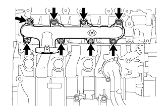
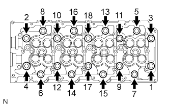
| 21. REMOVE CYLINDER HEAD SUB-ASSEMBLY |
Uniformly loosen the 18 cylinder head bolts in several passes in the sequence shown in the illustration. Then remove the 18 cylinder head bolts and 18 washers.
- NOTICE:
- Head warpage or cracking could result from removing bolts in the incorrect order.
Lift the cylinder head from the dowels on the cylinder block, and place the cylinder head on wooden blocks on a bench.
- NOTICE:
- Be careful not to damage the contact surfaces of the cylinder head and cylinder block.
- HINT:
- If the cylinder head is difficult to lift, use a screwdriver to pry between the cylinder head and block.
| 22. REMOVE CYLINDER HEAD GASKET |