Engine Unit (W/O Glow Plug Controller) -- Installation |
- NOTICE:
- When replacing the injectors (including shuffling the injectors between the cylinders), common rail or cylinder head, it is necessary to replace the injection pipes with new ones.
- When replacing the fuel supply pump, common rail, cylinder block, cylinder head, cylinder head gasket or timing gear case, it is necessary to replace the fuel inlet pipe with a new one.
- After removing the injection pipes, clean them with a brush and compressed air.
| 1. INSTALL FRONT NO. 1 ENGINE MOUNTING BRACKET LH |
Install the front No. 1 engine mounting bracket with the 4 bolts.
- Torque:
- 68 N*m{693 kgf*cm, 50 ft.*lbf}
| 2. INSTALL FRONT NO. 1 ENGINE MOUNTING BRACKET RH |
Install the front No. 1 engine mounting bracket with the 4 bolts.
- Torque:
- 68 N*m{693 kgf*cm, 50 ft.*lbf}
| 3. INSTALL ENGINE COOLANT TEMPERATURE SENSOR |
Install a new gasket to the engine coolant temperature sensor.
Install the engine coolant temperature sensor.
- Torque:
- 20 N*m{200 kgf*cm, 14 ft.*lbf}
Connect the engine coolant temperature sensor connector.
| 4. INSTALL CAMSHAFT POSITION SENSOR |
Apply a light coat of engine oil to the O-ring of the camshaft position sensor.
Install the camshaft position sensor with the bolt.
- Torque:
- 8.5 N*m{87 kgf*cm, 75 in.*lbf}
Connect the camshaft position sensor connector.
| 5. INSTALL CRANKSHAFT POSITION SENSOR |
Apply a light coat of engine oil to the O-ring of the crankshaft position sensor.
Install the crankshaft position sensor with the bolt.
- Torque:
- 8.5 N*m{87 kgf*cm, 75 in.*lbf}
Attach the 4 clips and connect the crankshaft position sensor connector.
- NOTICE:
- Insert the crankshaft position sensor wire harness into the protrusions of the timing gear cover.
| 6. INSTALL VANE PUMP ASSEMBLY |
Install a new O-ring to the vane pump.
Install the vane pump with the 2 nuts.
- Torque:
- 41 N*m{418 kgf*cm, 30 ft.*lbf}
| 7. INSTALL VACUUM PUMP ASSEMBLY |
Install 2 new O-rings to the vacuum pump.
Install the vacuum pump with the 2 nuts.
- Torque:
- 21 N*m{210 kgf*cm, 15 ft.*lbf}
| 8. INSTALL TIMING GEAR COVER INSULATOR (w/ EGR Cooler) |
Install the gear cover insulator with the bolt.
- Torque:
- 13 N*m{133 kgf*cm, 10 ft.*lbf}
| 9. INSTALL OIL COOLER COVER SUB-ASSEMBLY |
Install a new gasket and the oil cooler cover with the 13 bolts.
- Torque:
- 13 N*m{133 kgf*cm, 10 ft.*lbf}
Connect the No. 2 vacuum transmitting pipe with the 2 nuts.
- Torque:
- 13 N*m{133 kgf*cm, 10 ft.*lbf}
Connect the oil pressure switch connector.
| 10. INSTALL FUEL SUPPLY PUMP ASSEMBLY |
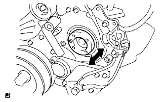
Check that the injection gear in the timing gear case moves back and forth smoothly.
 |
Install a new O-ring to the fuel supply pump.
Apply a light coat of engine oil to the O-ring.
Align the groove of the injection gear with the set key on the drive shaft.
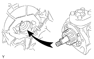 |
Install the fuel supply pump with the 2 nuts.
- Torque:
- 21 N*m{214 kgf*cm, 15 ft.*lbf}
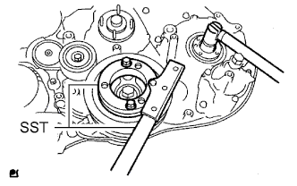
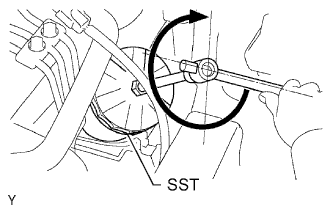
Set a new O-ring before tightening the set nut.
Using SST, hold the crankshaft pulley and install the set nut.
- SST
- 09213-58014
09330-00021
- Torque:
- 64 N*m{650 kgf*cm, 47 ft.*lbf}
 |
Install the pump drive shaft pulley and No. 2 camshaft timing pulley flange with the 4 bolts.
- Torque:
- 31 N*m{316 kgf*cm, 23 ft.*lbf}
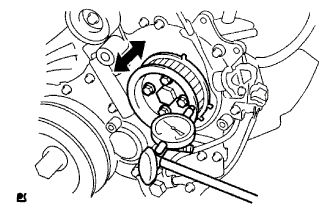
Move the pump drive shaft pulley back and forth to check the thrust clearance of the injection pump drive shaft.
- Standard thrust clearance:
- 0.15 to 0.55 mm (0.00590 to 0.0217 in.)
 |
Connect the fuel temperature sensor connector and suction control valve connector.
Connect the 2 fuel hoses.
| 11. INSTALL COMMON RAIL ASSEMBLY |
Install the common rail and No. 2 intake manifold insulator with the 2 bolts.
- Torque:
- 38 N*m{387 kgf*cm, 28 ft.*lbf}
Connect the 2 connectors.
| 12. INSTALL FUEL INLET PIPE SUB-ASSEMBLY |
Temporarily install the fuel inlet pipe with the union nuts.
- NOTICE:
- When replacing the fuel supply pump, it is necessary to replace the fuel inlet pipe with a new one.
- Keep the fuel inlet pipe free of foreign matter.
Using a 17 mm union nut wrench, tighten the fuel inlet pipe union nut on the common rail side.
- Torque:
- 35 N*m{357 kgf*cm, 26 ft.*lbf}
- NOTICE:
- Use the formula to calculate special torque values for situations where a union nut wrench is combined with a torque wrench (HILUX_TGN26 RM000004QR1003X.html).
Using a 17 mm union nut wrench, tighten the fuel inlet pipe union nut on the fuel supply pump side.
- Torque:
- 35 N*m{357 kgf*cm, 26 ft.*lbf}
- NOTICE:
- Use the formula to calculate special torque values for situations where a union nut wrench is combined with a torque wrench (HILUX_TGN26 RM000004QR1003X.html).
| 13. INSTALL OIL FILTER SUB-ASSEMBLY |
Check and clean the oil filter installation surface.
Apply clean engine oil to the gasket of a new oil filter.
Lightly screw the oil filter into place by hand. Tighten it until the gasket contacts the seat.
Using SST, tighten the oil filter. Depending on the space available, choose from the following.
- SST
- 09228-07501
If enough space is available, use a torque wrench to tighten the oil filter.
- Torque:
- 12 N*m{122 kgf*cm, 9 ft.*lbf}
If enough space is not available to use a torque wrench, tighten the oil filter 3/4 of a turn by hand or with a common wrench.
 |
| 14. INSTALL GLOW PLUG ASSEMBLY |
| 15. INSTALL INTAKE MANIFOLD |
| 16. INSTALL DIESEL THROTTLE BODY ASSEMBLY |
Install a new gasket and the diesel throttle body with the 2 bolts and 2 nuts.
- Torque:
- 20 N*m{204 kgf*cm, 15 ft.*lbf}
Connect the 2 connectors.
| 17. INSTALL WATER OUTLET |
Install a new gasket to the cylinder head as shown in the illustration.
Text in Illustration *1 Claw - HINT:
- Make sure the claws of the gasket face the water outlet.
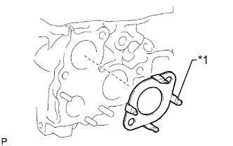 |
Install the water outlet with the 2 bolts.
- Torque:
- 19 N*m{194 kgf*cm, 14 ft.*lbf}
| 18. INSTALL THERMOSTAT |
Install a new gasket to the thermostat.
Text in Illustration *1 Gasket *2 Jiggle Valve *a CORRECT *b INCORRECT 
Upward - NOTICE:
- When installing the gasket to the thermostat, be careful not to deform the gasket. Make sure that the groove of the gasket is properly installed to the thermostat, as shown in the illustration.
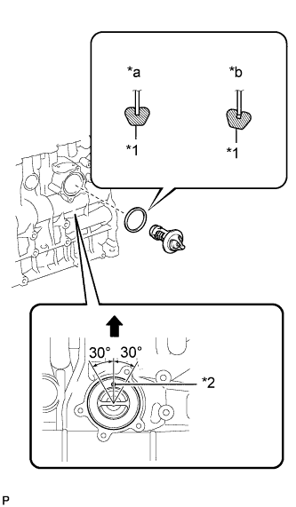 |
Insert the thermostat into the cylinder block with the jiggle valve facing straight upward.
- HINT:
- The jiggle valve may be set within 30° of either side of the prescribed position.
| 19. INSTALL WATER INLET |
Install the wire harness clamp bracket to the water inlet with the bolt.
- Torque:
- 13 N*m{128 kgf*cm, 9 ft.*lbf}
Install the water inlet with the 3 bolts.
- Torque:
- 13 N*m{133 kgf*cm, 10 ft.*lbf}
Connect the wire harness clamp.
| 20. INSTALL NO. 1 COMPRESSOR MOUNTING BRACKET (w/ Air Conditioning System) |
Install the No. 1 compressor mounting bracket with the 4 bolts.
- Torque:
- 45 N*m{459 kgf*cm, 33 ft.*lbf}
| 21. INSTALL V-RIBBED BELT TENSIONER ASSEMBLY |
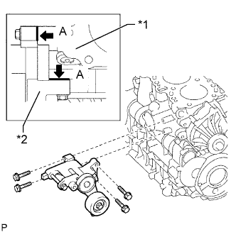
Install the V-ribbed belt tensioner with the 4 bolts.
- Torque:
- 21 N*m{214 kgf*cm, 15 ft.*lbf}
Text in Illustration *1 Cylinder Block *2 V-ribbed Belt Tensioner - HINT:
- Firmly press and hold the V-ribbed belt tensioner against the cylinder block to eliminate any gaps in the areas labeled A in the illustration. Then uniformly tighten the 4 bolts.
 |
| 22. INSTALL GENERATOR BRACKET |
Install the generator bracket with the bolt.
- Torque:
- 25 N*m{255 kgf*cm, 18 ft.*lbf}
| 23. INSTALL GENERATOR ASSEMBLY |
 |
Install the generator with the 2 bolts.
- Torque:
- for bolt A:
- 62 N*m{632 kgf*cm, 46 ft.*lbf}
- for bolt B:
- 25 N*m{255 kgf*cm, 18 ft.*lbf}
Install the generator wire with the nut.
- Torque:
- 9.8 N*m{100 kgf*cm, 87 in.*lbf}
Connect the generator connector.
| 24. INSTALL NO. 2 IDLE PULLEY ASSEMBLY |
Install the spacer, No. 2 idle pulley and pulley plate with the bolt.
- Torque:
- 45 N*m{459 kgf*cm, 33 ft.*lbf}
| 25. INSTALL EXHAUST MANIFOLD WITH TURBOCHARGER |
Install a new gasket and the exhaust manifold with turbocharger to the cylinder head with the 8 plate washers, 8 collars and 8 new nuts.
- Torque:
- 40 N*m{408 kgf*cm, 30 ft.*lbf}
| 26. INSTALL TURBOCHARGER STAY |
Temporarily install a new gasket and the turbocharger with 3 new nuts.
- HINT:
- It is easier to install the turbo oil inlet pipe if the 3 nuts are only loosely installed.
Temporarily install the turbo oil inlet pipe.
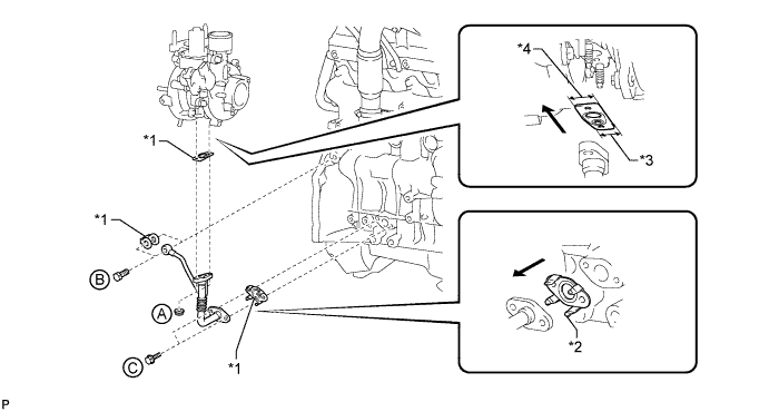
Text in Illustration *1 New Gasket *2 Claw *3 Narrow *4 Wide Outside - - - HINT:
- Before installing the turbo oil inlet pipe, clean it.
Install a new gasket and the turbo oil inlet pipe with the 2 nuts, but only loosely install the nuts.
- NOTICE:
- The notch (narrow part) of the gasket must face the engine.
Install a new gasket and the turbo oil inlet pipe with the 2 bolts, but only loosely install the bolts.
- NOTICE:
- The claws of the gasket must face the turbo oil inlet pipe.
Install a new gasket and the turbo oil inlet pipe with the union bolt, but only loosely install the union bolt.
Temporarily install the turbocharger stay with the 2 bolts and nut.
Tighten the 3 nuts of the turbocharger.
- Torque:
- 52 N*m{530 kgf*cm, 38 ft.*lbf}
Tighten the 2 nuts labeled A.
- Torque:
- 13 N*m{133 kgf*cm, 10 ft.*lbf}
Tighten the union bolt labeled B.
- Torque:
- 26 N*m{265 kgf*cm, 19 ft.*lbf}
Tighten the 2 bolts labeled C.
- Torque:
- 12 N*m{122 kgf*cm, 9 ft.*lbf}
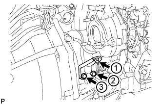
Tighten the 2 bolts and nut of the turbocharger stay in the order shown in the illustration.
- Torque:
- 38 N*m{387 kgf*cm, 28 ft.*lbf}
 |
| 27. INSTALL TURBINE OUTLET ELBOW |
Install a new gasket and the turbine outlet elbow with the 3 new nuts.
- Torque:
- 26 N*m{260 kgf*cm, 19 ft.*lbf}
| 28. INSTALL NO. 1 TURBO WATER HOSE |
Install the 2 No. 1 turbo water hoses.
| 29. INSTALL NO. 1 EXHAUST MANIFOLD HEAT INSULATOR |
Temporarily install the No. 1 exhaust manifold heat insulator with the bolt.
| 30. INSTALL NO. 1 TURBO INSULATOR |
Temporarily install the No. 1 turbo insulator with the 2 bolts.
Tighten the bolt of the No. 1 exhaust manifold heat insulator, and the 2 bolts of the No. 1 turbo insulator.
- Torque:
- 12 N*m{122 kgf*cm, 9 ft.*lbf}
| 31. INSTALL COMPRESSOR INLET ELBOW |
Install a new gasket and the compressor inlet elbow with the 2 nuts.
- Torque:
- 19 N*m{194 kgf*cm, 14 ft.*lbf}
Connect the 2 connectors to the turbocharger.
Attach the wire harness clamp.
| 32. INSTALL VENTILATION PIPE |
Connect the 2 ventilation hoses to the cylinder head cover and compressor inlet elbow.
Install the ventilation pipe to the cylinder head with the bolt.
- Torque:
- 20 N*m{204 kgf*cm, 15 ft.*lbf}
| 33. INSTALL INTERCOOLER SUPPORT BRACKET |
Install the intercooler support bracket with the 2 bolts.
- Torque:
- 32 N*m{326 kgf*cm, 24 ft.*lbf}
| 34. INSTALL NO. 2 INTERCOOLER SUPPORT BRACKET |
Install the No. 2 intercooler support bracket with the 2 bolts.
- Torque:
- 32 N*m{326 kgf*cm, 24 ft.*lbf}
| 35. INSTALL CRANKSHAFT PULLEY |
Align the keyway of the pulley with the key located on the crankshaft, and then slide the pulley into place to install it.
Using SST, install the pulley bolt.
- SST
- 09213-58014
09330-00021
- Torque:
- 365 N*m{3722 kgf*cm, 269 ft.*lbf}
 |
| 36. INSTALL NO. 1 TIMING BELT IDLER SUB-ASSEMBLY |
Using a 10 mm hexagon wrench, install a new washer and the No. 1 timing belt idler with the bolt.
- Torque:
- 35 N*m{357 kgf*cm, 26 ft.*lbf}
Check that the idler pulley moves smoothly.
If the idler pulley does not move smoothly, check the installation condition of the idler and washer.
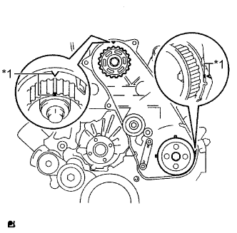
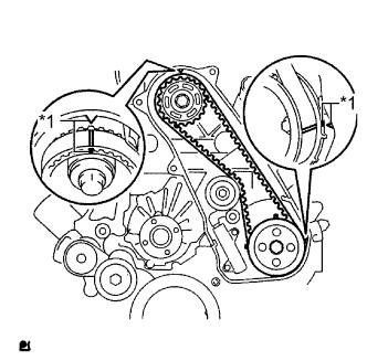
| 37. INSTALL TIMING BELT |
Check that the timing marks are aligned as shown in the illustration.
Text in Illustration *1 Timing Mark - NOTICE:
- Make sure that the engine is cold.
- When turning the crankshaft, the valve heads will hit against the piston. Do not turn the crankshaft more than necessary.
- HINT:
- If reusing the timing belt, align the points marked during removal, and install the belt with the arrow pointing in the direction of crankshaft revolution.
 |
Install the timing belt to the pump drive shaft pulley, camshaft timing pulley and No. 1 timing belt idler in sequence.
Place the tensioner upright. Then set a press on the top of the tensioner.
- NOTICE:
- Do not scratch or deform the rod end.
- Press in the tensioner rod.
- Protect the tip of the push rod with a cloth in order to prevent damage.
 |
Using the press, slowly push in the push rod using 981 to 9800 N (100 to 999 kgf, 220 to 2203 lbf) of force.
- NOTICE:
- Do not apply a load of over 9800 N (999 kgf, 2203 lbf) to the push rod.
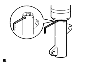
Align the holes of the push rod and housing. Then pass a 1.5 mm hexagon wrench through the holes to fix the push rod in place.
Temporarily install the timing belt tensioner with the 2 bolts while pushing the idler pulley toward the timing belt.
Tighten the 2 bolts.
- Torque:
- 13 N*m{133 kgf*cm, 10 ft.*lbf}
- NOTICE:
- Uniformly tighten the 2 bolts.
Remove the 1.5 mm hexagon wrench from the tensioner.
 |
Turn the crankshaft clockwise 720° and check that the timing marks are aligned as shown in the illustration.
Text in Illustration *1 Timing Mark
 |
| 38. INSTALL NO. 1 TIMING BELT COVER |
Install the timing belt cover and 6 washers with the 6 bolts.
- Torque:
- 6.0 N*m{61 kgf*cm, 53 in.*lbf}