INSTALL PUMP IMPELLER DRIVE PLATE (for Automatic Transmission)
INSPECT AND ADJUST CLUTCH COVER ASSEMBLY (for Manual Transmission)
INSTALL AUTOMATIC TRANSMISSION ASSEMBLY (for Automatic Transmission)
INSTALL MANUAL TRANSMISSION ASSEMBLY (for Manual Transmission)
Rear Crankshaft Oil Seal -- Installation |
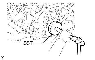
| 1. INSTALL REAR CRANKSHAFT OIL SEAL |
Apply MP grease to the lip of a new rear crankshaft oil seal.
Using SST and a hammer, tap in the oil seal until its surface is flush with the rear oil seal retainer edge.
- SST
- 09518-36030
09950-70010(09951-07200)
- NOTICE:
- The acceptable depth from the top of the oil seal retainer is 0 to 0.8 mm (0 to 0.315 in.)
- Keep the lip free from foreign matter.
- Do not tap the oil seal at an angle.
- Make sure that the oil seal is properly installed.
 |
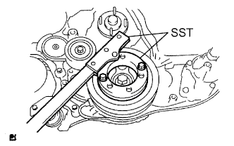
| 2. INSTALL PUMP IMPELLER DRIVE PLATE (for Automatic Transmission) |
Clean the bolts and their holes.
Using SST, hold the crankshaft pulley.
- SST
- 09213-58014
09330-00021
 |
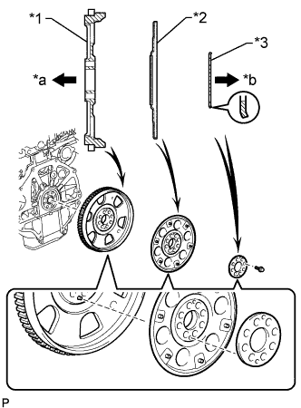
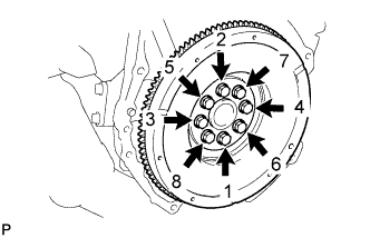
Install the flywheel and ring gear, the pump impeller drive plate and the rear drive plate spacer to the crankshaft.
Text in Illustration *1 Flywheel and Ring Gear *2 Pump Impeller Drive Plate *3 Rear Drive Plate Spacer *a Engine Side *b Transmission Side - NOTICE:
- Align either hole in the pump impeller drive plate and either hole in the rear drive plate spacer with the knock pin of the flywheel and ring gear, and then install the flywheel and ring gear, the pump impeller drive plate and the rear drive plate spacer to the crankshaft.
- HINT:
- As the rear drive plate spacer and pump impeller drive plate are not reversible, be sure to install them in the direction shown in the illustration.
 |
Install and uniformly tighten and tighten the 8 bolts in several steps in the sequence shown in the illustration.
- Torque:
- 178 N*m{1815 kgf*cm, 131 ft.*lbf}
- NOTICE:
- Do not start the engine for at least an hour after installing the flywheel and ring gear.
 |
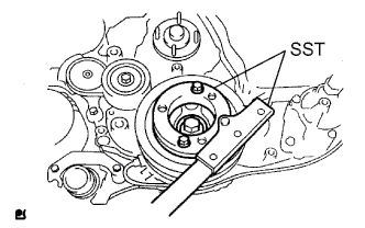
| 3. INSTALL FLYWHEEL SUB-ASSEMBLY (for Manual Transmission) |
Clean the bolts and their holes.
Apply adhesive to 2 or 3 threads at the end of each bolt.
- Adhesive:
- Toyota Genuine Adhesive 1324, Three Bond 1324 or equivalent
Using SST, hold the crankshaft pulley.
- SST
- 09213-58014
09330-00021
 |
Install the flywheel to the crankshaft.
Install and uniformly tighten the 8 bolts in the sequence shown in the illustration.
- Torque:
- 178 N*m{1815 kgf*cm, 131 ft.*lbf}
- NOTICE:
- Do not start the engine for at least 1 hour after installation.
 |
| 4. INSTALL CLUTCH DISC ASSEMBLY (for Manual Transmission) |
Insert SST into the clutch disc. Then insert SST (together with the clutch disc) into the flywheel.
- SST
- 09301-00110
- NOTICE:
- Be sure to install the clutch disc so that it is facing in the correct direction.
 |
| 5. INSTALL CLUTCH COVER ASSEMBLY (for Manual Transmission) |
Align the matchmarks on the clutch cover and flywheel.
Text in Illustration *1 Matchmark
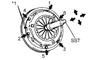 |
Tighten the 6 bolts as described below.
Determine the first bolt to be tightened by choosing the bolt closest to the knock pin.
Uniformly tighten the 6 bolts in diametrically opposite pairs relative to the position of the first bolt. Use the illustration as a reference.
Lightly move SST up and down, and right and left.
- SST
- 09301-00110
Check that the disc is in the center, and then tighten the bolts.
- Torque:
- 19 N*m{195 kgf*cm, 14 ft.*lbf}
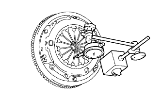
| 6. INSPECT AND ADJUST CLUTCH COVER ASSEMBLY (for Manual Transmission) |
Using a dial indicator with a roller instrument, measure the diaphragm spring tip alignment.
- Maximum misalignment:
- 0.5 mm (0.020 in.)
If the misalignment is more than the maximum, use SST to adjust the diaphragm spring tip alignment.
- SST
- 09333-00013
 |
| 7. INSTALL AUTOMATIC TRANSMISSION ASSEMBLY (for Automatic Transmission) |
| 8. INSTALL MANUAL TRANSMISSION ASSEMBLY (for Manual Transmission) |
- for 2WD: (HILUX_TGN26 RM0000011B000RX.html)
- for 4WD: (HILUX_TGN26 RM0000011AJ00IX.html)