Cylinder Head -- Replacement |
| 1. REPLACE VALVE GUIDE BUSH |
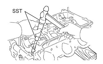
Heat the cylinder head to between 80 and 100°C (176 and 212°F).
Place the cylinder head on wooden blocks.
Using SST and a hammer, tap out the intake valve guide bushes.
- SST
- 09201-10000(09201-01050)
09950-70010(09951-07100)
 |
Using a caliper gauge, measure the valve guide bush bore diameter of the cylinder head.
- Standard Bush Bore Diameter:
Item Specified Condition STD 10.285 to 10.306 mm (0.4049 to 0.4057 in.) O/S 0.05 10.335 to 10.356 mm (0.4069 to 0.4077 in.)
Select a new valve guide bush.
- New Guide Bush:
Item Specified Condition Bush Bore Diameter 10.285 to 10.306 mm (0.4049 to 0.4057 in.) 10.335 to 10.356 mm (0.4069 to 0.4077 in.) Bush to be Used STD O/S 0.05
If the bush bore diameter of the cylinder head is more than 10.356 mm (0.4077 in.), replace the cylinder head.- New Guide Bush Diameter:
Item Specified Condition STD 10.333 to 10.344 mm (0.4068 to 0.4072 in.) O/S 0.05 10.383 to 10.394 mm (0.4088 to 0.4092 in.)
- HINT:
- Different bushes are used for the intake and exhaust.
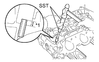
Heat the cylinder head to between 80 and 100°C (176 and 212°F).
Place the cylinder head on wooden blocks.
Using SST, tap in the valve guide bushes to the specified protrusion height.
- SST
- 09201-10000(09201-01050)
09950-70010(09951-07100)
- Protrusion height:
- 9.30 to 9.70 mm (0.366 to 0.382 in.)
Text in Illustration *1 Protrusion Height
 |
Using a sharp 5.5 mm reamer, ream the valve guide bushes to obtain the specified clearance.
- Standard Oil Clearance:
Item Specified Condition Intake 0.025 to 0.060 mm (0.000984 to 0.00236 in.) Exhaust 0.030 to 0.065 mm (0.00118 to 0.00256 in.)
 |
| 2. REPLACE UNION |
- NOTICE:
- If a union is deformed or its threads are damaged, replace it.
Remove the 2 unions.

Text in Illustration *a Front Side of RH *b Intake Side of LH
Apply adhesive to 2 or 3 threads at the bolt ends of new unions.
- Adhesive:
- Toyota Genuine Seal Adhesive 1324, Three Bond 1324 or equivalent
Using a 12 mm deep socket wrench, install the 2 unions.
- Torque:
- 15 N*m{150 kgf*cm, 11 ft.*lbf}
| 3. REPLACE TIGHT PLUG |
- NOTICE:
- If water leaks from the tight plug or the plug is corroded, replace it.
Remove the tight plugs.
Apply adhesive around new tight plugs.
- Adhesive:
- Toyota Genuine Adhesive 1324, Three Bond 1324 or equivalent
Using SST and a hammer, tap in the tight plugs to the standard depth.
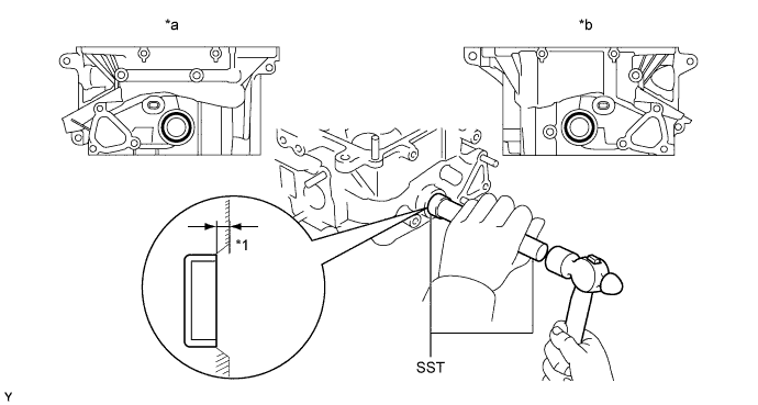
Text in Illustration *1 Standard Depth - - *a RH *b LH - SST
- 09950-60010(09951-00250)
09950-70010(09951-07150)
- Standard depth:
- 1.5 mm (0.0591 in.)
| 4. REPLACE STRAIGHT PIN |
- NOTICE:
- If a straight pin is deformed, replace it.
Using a plastic-faced hammer, tap in new straight pins as shown in the illustration.
- Standard Protrusion Height:
Item Specified Condition Pin A 17.5 to 19.5 mm (0.689 to 0.768 in.) Pin B 7.5 to 8.5 mm (0.295 to 0.335 in.) Pin C 7.0 to 9.0 mm (0.276 to 0.354 in.)

Text in Illustration *1 Protrusion Height - - *a LH *b RH *c Front Side *d Upper Side *e Intake Manifold Side - -
| 5. REPLACE RING PIN |
- NOTICE:
- It is not necessary to remove a ring pin unless it is being replaced.
Using a plastic-faced hammer, tap in new ring pins to the specified protrusion height.
- Standard protrusion height:
- 2.7 to 3.3 mm (0.106 to 0.0969 in.)

Text in Illustration *A Engine Front - - *a RH *b LH *1 Protrusion Height - -