Cylinder Head -- Inspection |
| 1. CLEAN CYLINDER HEAD SUB-ASSEMBLY |
Using a gasket scraper, remove all the gasket material from the surface which contacts the cylinder block.
- NOTICE:
- Be careful not to scratch the surface which contacts the cylinder block.
Using a wire brush, remove all the carbon from the combustion chambers.
- NOTICE:
- Be careful not to scratch the cylinder block contact surface.
Using a valve guide bushing brush and solvent, clean all the guide bushes.
 |
Using a soft brush and solvent, thoroughly clean the cylinder head.
| 2. INSPECT CYLINDER HEAD SUB-ASSEMBLY |
Using a precision straightedge and feeler gauge, measure the surfaces that contact the cylinder block and manifolds for warpage.
- Maximum warpage:
- 0.10 mm (0.00394 in.)
If the warpage is more than the maximum, replace the cylinder head sub-assembly.Text in Illustration *a Cylinder Block Side *b Intake Manifold Side *c Exhaust Manifold Side
 |
| 3. INSPECT CYLINDER HEAD FOR CRACKS |
Using a dye penetrant, check the intake ports, exhaust ports and cylinder head surface for cracks.
If cracked, replace the cylinder head sub-assembly.
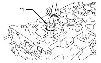
| 4. CLEAN VALVE SEAT |
Using a 45° carbide cutter, resurface the valve seats.
Text in Illustration *1 45° Carbide Cutter - HINT:
- Only remove the amount of metal necessary to clean the seats.
 |
| 5. CLEAN VALVE |
Clean the valves.
Using a gasket scraper, chip off any carbon from the valve head.
Using a wire brush, thoroughly clean the valve.
| 6. INSPECT VALVE |
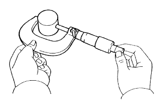
Using a micrometer, measure the diameter of the valve stem.
- Standard Valve Stem Diameter:
Item Specified Condition Intake 5.470 to 5.485 mm (0.2154 to 0.2159 in.) Exhaust 5.465 to 5.480 mm (0.2152 to 0.2158 in.)
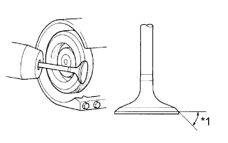
Check the valve face angle.
Text in Illustration *1 Valve Face Angle Grind the valve sufficiently to remove pits and carbon.
Check that the valve is ground to the correct valve face angle.
- Standard valve face angle:
- 44.5°
 |
Using a vernier caliper, measure the valve head margin thickness.
Text in Illustration *1 Margin Thickness - Standard margin thickness:
- 1.0 mm (0.0394 in.)
- Minimum margin thickness:
- 0.5 mm (0.0197 in.)
 |
Using a vernier caliper, measure the overall valve length.
- Standard Overall Length:
Item Specified Condition Intake 106.95 mm (4.21 in.) Exhaust 105.80 mm (4.17 in.)
- Minimum Overall Length:
Item Specified Condition Intake 106.40 mm (4.19 in.) Exhaust 105.30 mm (4.15 in.)
Check the surface of the valve stem tip for wear.
- NOTICE:
- Do not grind off more than the minimum length.
 |
| 7. INSPECT VALVE GUIDE BUSH OIL CLEARANCE |
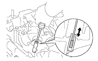
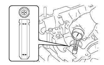
Using a caliper gauge, measure the inside diameter of the valve guide bush.
- Bush inside diameter:
- 5.510 to 5.530 mm (0.217 to 0.218 in.)
 |
Subtract the valve stem diameter measurement from the valve guide bush inside diameter measurement.
- Standard Oil Clearance:
Item Specified Condition Intake 0.025 to 0.060 mm (0.000984 to 0.00236 in.) Exhaust 0.030 to 0.065 mm (0.00118 to 0.00256 in.)
- Maximum Oil Clearance:
Item Specified Condition Intake 0.08 mm (0.00315 in.) Exhaust 0.10 mm (0.00394 in.)
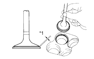
| 8. INSPECT VALVE SEAT |
Apply a light coat of Prussian blue to the valve face.
Lightly press the valve face against the valve seat.
- NOTICE:
- Do not rotate the valve.
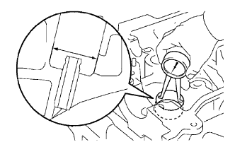
Check the valve face and valve seat using the following procedure.
Text in Illustration *1 Width Check that Prussian blue appears 360° around the valve face.
If not, replace the valve.If Prussian blue appears 360° around the valve seat, the guide and valve face are concentric.
If not, resurface the valve seat.Check that the valve seat contact is in the middle of the valve face with the valve seat width between 1.0 and 1.4 mm (0.0394 to 0.0551 in.).
 |
| 9. INSPECT INNER COMPRESSION SPRING |
Using a vernier caliper, measure the free length of the inner compression spring.
- Standard free length:
- 47.80 mm (1.88 in.)
 |
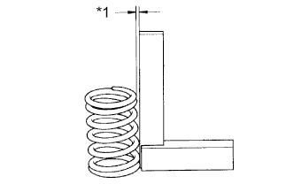
Using a steel square, measure the deviation of the inner compression spring.
- Maximum deviation:
- 2.0 mm (0.0787 in.)
If the deviation is more than the maximum, replace the inner compression spring.Text in Illustration *1 Deviation
 |
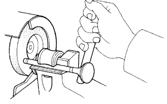
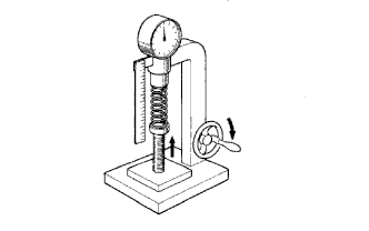
Using a spring tester, measure the tension of the valve spring when it is compressed to the specified installation length.
- Standard installed tension:
- 186 to 206 N (19 to 21 kgf, 42 to 46 lbf) at 33.3 mm (1.31 in.)
 |
| 10. INSPECT CAMSHAFT THRUST CLEARANCE |
Install the camshafts (HILUX_TGN26 RM000000YMM00CX_01_0033.html).
 |
Using a dial indicator, measure the thrust clearance while moving the camshaft back and forth.
- Standard thrust clearance:
- 0.04 to 0.09 mm (0.0157 to 0.0354 in.)
- Maximum thrust clearance:
- 0.11 mm (0.00433 in.)
If necessary, replace the camshaft bearing caps and cylinder head as a set.
| 11. INSPECT VALVE LIFTER |
Using a micrometer, measure the lifter diameter.
- Standard lifter diameter:
- 30.966 to 30.976 mm (1.219 to 1.220 in.)
 |
Using a caliper gauge, measure the valve lifter bore diameter of the cylinder head.
- Standard lifter bore diameter:
- 31.009 to 31.025 mm (1.2208 to 1.2215 in.)
 |
Subtract the valve lifter diameter measurement from the valve lifter bore diameter measurement.
- Standard oil clearance:
- 0.033 to 0.059 mm (0.00130 to 0.00232 in.)
- Maximum oil clearance:
- 0.08 mm (0.00315 in.)