Engine Unit -- Inspection |
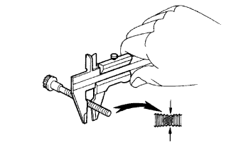
| 1. INSPECT CYLINDER HEAD SET BOLT |
Using a vernier caliper, measure the outside thread diameter of the bolt.
- Standard diameter:
- 10.85 to 11.0 mm (0.427 to 0.433 in.)
- Minimum diameter:
- 10.7 mm (0.421 in.)
 |
| 2. INSPECT CAMSHAFT |
Inspect the camshaft runout.
Place the camshaft on V-blocks.
Using a dial indicator, measure the circle runout at the center journal.
- Maximum runout:
- 0.06 mm (0.00236 in.)
- HINT:
- Check the oil clearance after replacing the camshaft.
Using a micrometer, measure the cam lobe height.
- Standard Cam Lobe Height:
Item Specified Condition Intake camshaft 44.168 to 44.268 mm (1.739 to 1.743 in.) Exhaust camshaft 44.580 to 44.680 mm (1.755 to 1.759 in.)
- Minimum Cam Lobe Height:
Item Specified Condition Intake camshaft 44.018 mm (1.733 in.) Exhaust camshaft 44.430 mm (1.749 in.)
Using a micrometer, measure the journal diameter.
- Standard Journal Diameter:
Item Specified Condition No. 1 journal 35.971 to 35.985 mm (1.416 to 1.417 in.) Other journals 22.959 to 22.975 mm (0.9039 to 0.9045 in.)
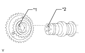
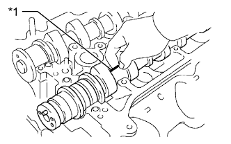
| 3. INSPECT CAMSHAFT TIMING GEAR ASSEMBLY |
Fix the camshaft in place.
- NOTICE:
- Be careful not to damage the camshaft.
Lightly press and turn the camshaft timing gear against the camshaft and press harder after the pin enters the hole.
Text in Illustration *1 Pin Hole *2 Straight Pin - NOTICE:
- Be sure not to turn the camshaft timing gear in the retard direction.
 |
Check that there is no clearance between the camshaft timing gear flange and camshaft.
Tighten the flange bolt while holding the camshaft.
- Torque:
- 100 N*m{1020 kgf*cm, 74 ft.*lbf}
Check the lock of the camshaft timing gear.
Fix the camshaft in place and confirm that the camshaft timing gear is locked.
- NOTICE:
- Be careful not to damage the camshaft.
Release the lock pin.
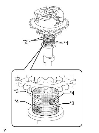
Cover the 4 oil paths of the cam journal with vinyl tape as shown in the illustration.
Text in Illustration *1 Advance Side Path *2 Retard Side Path *3 Open *4 Closed 
Rubber 
Vinyl Tape - HINT:
- One of the 2 grooves on the cam journal is for retard side paths (upper) and the other is for advance side paths (lower). Each groove has 2 oil holes. Plug one of the oil holes in each groove with a piece of rubber as shown in the illustration before wrapping the cam journal with tape.
Prick a hole in the tape at the 2 oil holes not plugged with rubber pieces.
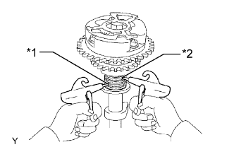
Apply compressed air at approximately 200 kPa (2.0 kgf/cm2, 28 psi) to the two broken paths (the advance side path and the retard side path).
Text in Illustration *1 Advance Side Path *2 Retard Side Path - NOTICE:
- Cover the paths with a cloth to avoid oil splashing.
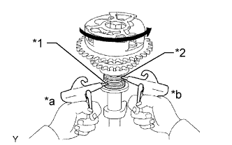
Confirm that the camshaft timing gear rotates in the advance direction when reducing the air pressure applied to the retard path.
Text in Illustration *1 Advance Side Path *2 Retard Side Path *a Hold Pressure *b Decompress - HINT:
- When the lock pin is released, the camshaft timing gear rotates in the advance direction.
When the camshaft timing gear comes to the most advanced position, release the air pressure from the retard side path, and then release the air pressure from the advance side path.
- NOTICE:
- The camshaft timing gear occasionally shifts to the retard side abruptly if air compression at the advanced side path is released first. This often results in the breakage of the lock pin.
 |
Check for smooth rotation.
Except the position where the lock pin meets at the most retarded angle, turn the camshaft timing gear back and forth and check the movable range and that there is no disturbance.
- Standard:
- Moves smoothly in the range of about a 31° range
- NOTICE:
- Be sure to perform this check by hand, instead of with air pressure.
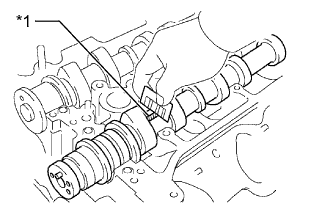
Check the lock in the most retarded position.
Confirm that the camshaft timing gear is locked at the most retarded position.
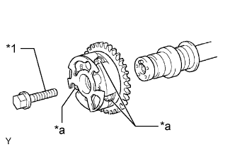
Remove the set bolt and camshaft timing gear.
Text in Illustration *1 Set Bolt *a Do not remove - NOTICE:
- Be sure not to remove the other 3 bolts.
 |
| 4. INSPECT CHAIN SUB-ASSEMBLY |
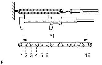
Using a spring scale, pull the chain with a force of 147 N (15 kgf, 33.1 lbf) and measure the length of the chain using a vernier caliper.
- Maximum chain elongation:
- 146.8 mm (5.78 in.)
Text in Illustration *1 Measurement Area - HINT:
- Perform the measurement at 3 random places. If a measurement is more than the maximum, replace the chain.
 |
| 5. INSPECT NO. 2 CHAIN SUB-ASSEMBLY |
Using a spring scale, pull the No. 2 chain with a force of 147 N (15 kgf, 33.1 lbf) and measure the length of the No. 2 chain using a vernier caliper.
- Maximum chain elongation:
- 146.8 mm (5.78 in.)
- HINT:
- Perform the measurement at 3 random places. If a measurement is more than the maximum, replace the No. 2 chain.
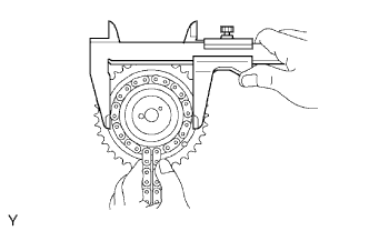
| 6. INSPECT CAMSHAFT TIMING GEAR ASSEMBLY |
Wrap the chain around the larger gear of the camshaft timing gear assembly.
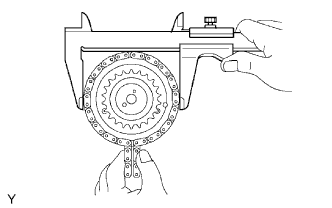 |
Using a vernier caliper, measure the timing gear together with the chain.
- Minimum gear diameter (with chain):
- 115.5 mm (4.55 in.)
- HINT:
- The vernier caliper must contact the chain rollers for the measurement.
- If the diameter is less than the minimum, replace the chain and camshaft timing gear assembly.
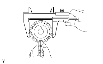
Wrap the No. 2 chain around the smaller gear of the camshaft timing gear assembly.
 |
Using a vernier caliper, measure the timing gear together with the No. 2 chain.
- Minimum gear diameter (with chain):
- 73.1 mm (2.88 in.)
- HINT:
- The vernier caliper must contact the No. 2 chain rollers for the measurement.
- If the diameter is less than the minimum, replace the No. 2 chain and camshaft timing gear assembly.
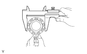
| 7. INSPECT CAMSHAFT TIMING GEAR OR SPROCKET |
Wrap the No. 2 chain around the camshaft timing gear or sprocket.
 |
Using a vernier caliper, measure the camshaft timing gear or sprocket diameter together with the No. 2 chain.
- Minimum gear diameter (with chain):
- 73.1 mm (2.88 in.)
- HINT:
- The vernier caliper must contact the No. 2 chain rollers for the measurement.
- If the diameter is less than the minimum, replace the No. 2 chain and camshaft timing gear or sprocket.
| 8. INSPECT CRANKSHAFT TIMING GEAR OR SPROCKET |
Wrap the chain around the crankshaft timing gear or sprocket.
 |
Using a vernier caliper, measure the crankshaft timing gear or sprocket diameter together with the chain.
- Minimum gear diameter (with chain):
- 61.0 mm (2.40 in.)
- HINT:
- The vernier caliper must contact the chain rollers for the measurement.
- If the diameter is less than the minimum, replace the chain and crankshaft timing gear or sprocket.
| 9. INSPECT NO. 1 IDLE GEAR SHAFT |
Wrap the chain around the idle gear.
|
Using a vernier caliper, measure the idle gear together with the chain.
- Minimum gear diameter (with chain):
- 61.0 mm (2.40 in.)
- HINT:
- The vernier caliper must contact the chain rollers for the measurement.
- If the diameter is less than the minimum, replace the chain and No. 1 idle gear shaft.
| 10. INSPECT IDLE GEAR SHAFT OIL CLEARANCE |
Using a micrometer, measure the No. 1 idle gear shaft diameter.
- Standard No. 1 idle gear shaft diameter:
- 22.987 to 23.000 mm (0.905 to 0.906 in.)
Using a caliper gauge, measure the inside diameter of the No. 1 idle gear.
- Standard No. 1 idle gear inside diameter:
- 23.02 to 23.03 mm (0.906 to 0.907 in.)
Subtract the No. 1 idle gear shaft diameter measurement from the No. 1 idle gear inside diameter measurement.
- Standard oil clearance:
- 0.020 to 0.043 mm (0.000787 to 0.00169 in.)
- Maximum oil clearance:
- 0.093 mm (0.00366 in.)
| 11. INSPECT NO. 1 CHAIN TENSIONER ASSEMBLY |
Check that the plunger moves smoothly when the ratchet pawl is raised with your finger.
Text in Illustration *a Raise *b Move *c Lock
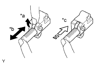 |
Release the ratchet pawl and check that the plunger is locked in place by the ratchet pawl and does not move when pushed with your finger.
If necessary, replace the No. 1 chain tensioner assembly.
| 12. INSPECT NO. 2 CHAIN TENSIONER ASSEMBLY |
Check that the plunger moves smoothly.
Text in Illustration *a Depth *b Moves Smoothly
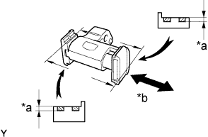 |
Measure the depth of wear of the No. 2 chain tensioner.
- Maximum depth:
- 1.0 mm (0.0394 in.)
| 13. INSPECT NO. 3 CHAIN TENSIONER ASSEMBLY |
Check that the plunger moves smoothly.
Text in Illustration *a Depth *b Moves Smoothly
 |
Measure the depth of wear of the No. 3 chain tensioner.
- Maximum depth:
- 1.0 mm (0.0394 in.)
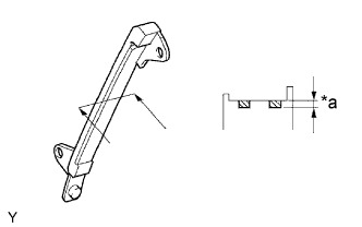
| 14. INSPECT CHAIN TENSIONER SLIPPER |
Measure the depth of wear of the chain tensioner slipper.
- Maximum depth:
- 1.0 mm (0.0394 in.)
If the depth is more than the maximum, replace the chain tensioner slipper.Text in Illustration *a Depth
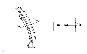 |
| 15. INSPECT NO. 1 CHAIN VIBRATION DAMPER |
Measure the depth of wear of the No. 1 chain vibration damper.
- Maximum depth:
- 1.0 mm (0.0394 in.)
If the depth is more than the maximum, replace the No. 1 chain vibration damper.Text in Illustration *a Depth
 |
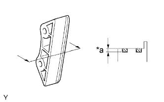
| 16. INSPECT NO. 2 CHAIN VIBRATION DAMPER |
Measure the depth of wear of the No. 2 chain vibration damper.
- Maximum depth:
- 1.0 mm (0.0394 in.)
If the depth is more than the maximum, replace the No. 2 chain vibration damper.Text in Illustration *a Depth
 |
| 17. INSPECT CAMSHAFT OIL CLEARANCE |
Clean the camshaft bearing caps, camshaft bearings and camshaft journals.
Install the camshaft bearing.
Place the camshaft on the cylinder head.
Lay a strip of Plastigage across each camshaft journal.
Text in Illustration *1 Plastigage
 |
Install the camshaft bearing caps (HILUX_TGN26 RM000000YMM00CX_01_0033.html).
- NOTICE:
- Do not turn the camshafts.
Remove the camshaft bearing caps (HILUX_TGN26 RM000000YML00CX_01_0028.html).
Measure the Plastigage at its widest point.
- Standard Oil Clearance (for Cylinder Head RH):
Item Specified Condition No. 1 journal
(for Intake Side)0.008 to 0.038 mm (0.000315 to 0.00150 in.) No. 1 journal
(for Exhaust Side)0.040 to 0.079 mm (0.00157 to 0.00311 in.) Other journals 0.025 to 0.062 mm (0.000984 to 0.00244 in.)
- Standard Oil Clearance (for Cylinder Head LH):
Item Specified Condition No. 1 journal 0.040 to 0.079 mm (0.00157 to 0.00311 in.) Other journals 0.025 to 0.062 mm (0.000984 to 0.00244 in.)
- Maximum Oil Clearance (for Cylinder Head RH):
Item Specified Condition No. 1 journal 0.07 mm (0.00276 in.) Other journals 0.10 mm (0.00394 in.)
- Maximum oil clearance (for cylinder head LH):
- 0.10 mm (0.00394 in.)
If the oil clearance is more than the maximum, replace the camshaft bearings and/or camshaft.Text in Illustration *1 Plastigage
If necessary, replace the camshaft bearing caps and cylinder head as a set.- Reference:
Item Specified Condition Cylinder head journal bore diameter 40.009 to 40.017 mm (1.5752 to 1.5755 in.) Camshaft bearing center wall thickness (Mark "2") 2.004 to 2.008 mm (0.0789 to 0.0791 in.) Camshaft journal diameter 35.971 to 35.985 mm (1.4165 to 1.4167 in.)
 |
Remove the Plastigage completely.
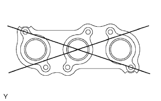
| 18. INSPECT EXHAUST MANIFOLD FOR FLATNESS |
Using a precision straightedge and feeler gauge, measure the warpage of the surface which contacts the cylinder head.
- Maximum warpage:
- 0.70 mm (0.0276 in.)
 |
| 19. INSPECT INTAKE MANIFOLD FOR FLATNESS |
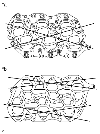 |
Using a precision straightedge and feeler gauge, measure the warpage of the surfaces which contact the cylinder head and intake air surge tank.
- Maximum Warpage:
Item Specified Condition Intake air surge tank side 0.80 mm (0.0315 in.) Cylinder head side 0.20 mm (0.00787 in.)
If the warpage is more than the maximum, replace the intake manifold.Text in Illustration *a Intake Air Surge Tank Side *b Cylinder Head Side