REMOVE CYLINDER BLOCK WATER DRAIN COCK SUB-ASSEMBLY
REMOVE VVT SENSOR (for Bank 1)
REMOVE VVT SENSOR (for Bank 2)
REMOVE CAMSHAFT TIMING OIL CONTROL VALVE ASSEMBLY (for Bank 1)
REMOVE CAMSHAFT TIMING OIL CONTROL VALVE ASSEMBLY (for Bank 2)
REMOVE CRANK POSITION SENSOR
REMOVE OIL CONTROL VALVE FILTER
REMOVE OIL FILTER SUB-ASSEMBLY
REMOVE OIL COOLER ASSEMBLY
REMOVE OIL FILTER BRACKET SUB-ASSEMBLY
REMOVE PCV VALVE
REMOVE SPARK PLUG
REMOVE WATER INLET ASSEMBLY
REMOVE CYLINDER HEAD COVER SUB-ASSEMBLY
REMOVE CYLINDER HEAD COVER SUB-ASSEMBLY LH
SET NO. 1 CYLINDER TO TDC/COMPRESSION
REMOVE CRANKSHAFT PULLEY
REMOVE OIL PAN DRAIN PLUG
REMOVE NO. 2 OIL PAN SUB-ASSEMBLY
REMOVE OIL STRAINER SUB-ASSEMBLY
REMOVE OIL PAN SUB-ASSEMBLY
REMOVE TIMING CHAIN COVER SUB-ASSEMBLY
REMOVE ENGINE WATER PUMP ASSEMBLY
REMOVE FRONT CRANKSHAFT OIL SEAL
REMOVE NO. 1 CHAIN TENSIONER ASSEMBLY
REMOVE CHAIN TENSIONER SLIPPER
REMOVE NO. 1 IDLE GEAR SHAFT
REMOVE NO. 2 CHAIN VIBRATION DAMPER
REMOVE CHAIN SUB-ASSEMBLY
REMOVE CRANKSHAFT TIMING GEAR OR SPROCKET
REMOVE NO. 1 CHAIN VIBRATION DAMPER
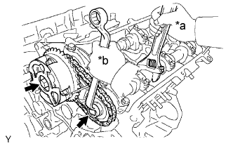
REMOVE CAMSHAFT TIMING GEARS AND NO. 2 CHAIN (for Bank 1)
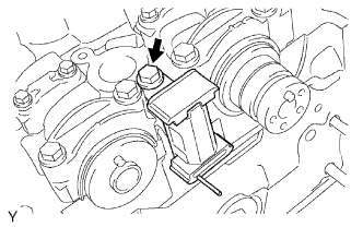
REMOVE NO. 2 CHAIN TENSIONER ASSEMBLY
REMOVE CAMSHAFT TIMING GEARS AND NO. 2 CHAIN (for Bank 2)
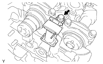
REMOVE NO. 3 CHAIN TENSIONER ASSEMBLY
REMOVE CAMSHAFT AND NO. 2 CAMSHAFT
REMOVE NO. 1 CAMSHAFT BEARING
REMOVE NO. 2 CAMSHAFT BEARING
REMOVE NO. 3 CAMSHAFT SUB-ASSEMBLY AND NO. 4 CAMSHAFT SUB-ASSEMBLY
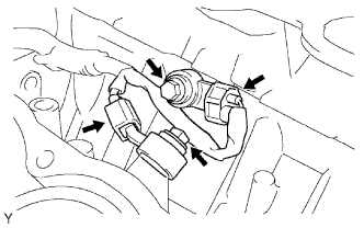
REMOVE REAR WATER BY-PASS JOINT
REMOVE CYLINDER HEAD LH
REMOVE CYLINDER HEAD SUB-ASSEMBLY
REMOVE CYLINDER HEAD GASKET
REMOVE NO. 2 CYLINDER HEAD GASKET
REMOVE NO. 1 WATER OUTLET PIPE
REMOVE KNOCK SENSOR
REMOVE REAR ENGINE OIL SEAL RETAINER
REMOVE REAR CRANKSHAFT OIL SEAL
REMOVE VALVE LIFTER
Engine Unit -- Disassembly |
| 1. REMOVE CYLINDER BLOCK WATER DRAIN COCK SUB-ASSEMBLY |
Remove the 2 cylinder block water drain cocks.
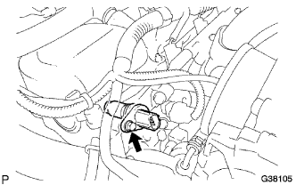
| 2. REMOVE VVT SENSOR (for Bank 1) |
Disconnect the VVT sensor connector.
Remove the bolt and VVT sensor.
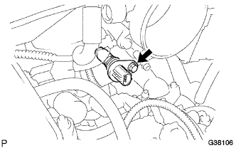
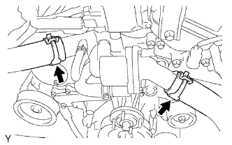
| 3. REMOVE VVT SENSOR (for Bank 2) |
Disconnect the No. 4 and No. 5 water by-pass hoses.
Disconnect the VVT sensor connector.
Remove the bolt and VVT sensor.
| 4. REMOVE CAMSHAFT TIMING OIL CONTROL VALVE ASSEMBLY (for Bank 1) |
Disconnect the camshaft timing oil control valve connector.
Remove the bolt and camshaft timing oil control valve.
Remove the O-ring from the camshaft timing oil control valve.
| 5. REMOVE CAMSHAFT TIMING OIL CONTROL VALVE ASSEMBLY (for Bank 2) |
Disconnect the camshaft timing oil control valve connector.
Remove the bolt and camshaft timing oil control valve.
Remove the O-ring from the camshaft timing oil control valve.
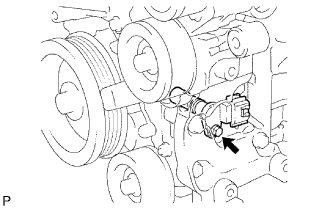
| 6. REMOVE CRANK POSITION SENSOR |
Disconnect the crankshaft position sensor connector.
Remove the bolt and crankshaft position sensor.
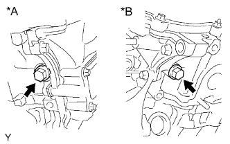
| 7. REMOVE OIL CONTROL VALVE FILTER |
Remove the plug, filter and gasket from each cylinder head.
Text in Illustration*A
| for Bank 1
|
*B
| for Bank 2
|
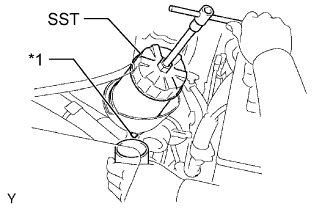
| 8. REMOVE OIL FILTER SUB-ASSEMBLY |
When not using drain hose:
Remove the drain pipe cap from the drain pipe.
Text in Illustration*1
| Drain Pipe
|
While removing the oil filter with SST, collect the oil from the oil filter in a container.
- SST
- 09228-07501
Install the drain pipe cap.
Clean the oil catch plate.
- HINT:
- When using a drain hose, perform the following procedure.
Using SST, remove the oil filter.
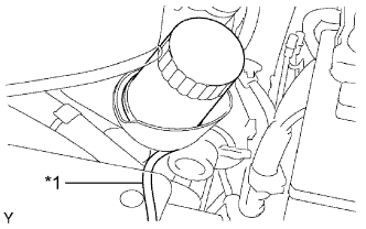
When using drain hose:
Remove the drain pipe cap from the drain pipe.
Connect a drain hose to the oil filter bracket.
Text in Illustration*1
| Drain Hose
|
- HINT:
- Drain hose inside diameter: 8 mm (0.315 in.)
- Drain hose length: Approximately 900 mm (2.95 ft.)
Feed the drain hose down through the engine under cover, and put the drain oil container beneath the drain hose to collect the oil from the oil filter.
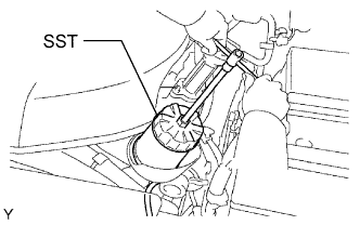
Using SST, remove the oil filter.
- SST
- 09228-07501
Remove the drain hose and install the drain pipe cap.
Clean the oil catch plate.
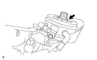
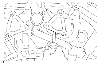
| 9. REMOVE OIL COOLER ASSEMBLY |
Disconnect the 2 hoses from the oil cooler.
Remove the union bolt, plate washer and oil cooler.
Remove the O-ring from the oil cooler.
| 10. REMOVE OIL FILTER BRACKET SUB-ASSEMBLY |
Remove the 3 bolts, 2 nuts, oil filter bracket and gasket.
Text in Illustration
| Bolt
|

| Nut
|
Loosen the hose clamp and disconnect the PCV hose from the PCV valve.
Remove the PCV valve.
Remove the 6 spark plugs.
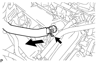
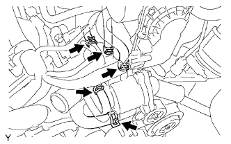
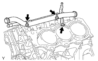
| 13. REMOVE WATER INLET ASSEMBLY |
Remove the 2 radiator hoses from the water inlet assembly.
Disconnect the 5 water by-pass hoses.
Remove the 5 bolts and water inlet assembly.
Remove the O-ring from the water outlet pipe.
Remove the gasket from the engine water pump.
| 14. REMOVE CYLINDER HEAD COVER SUB-ASSEMBLY |
Remove the 10 bolts, 3 seal washers, 2 nuts, cylinder head cover and gasket.
Text in Illustration
| Bolt
|
| Nut
|
| 15. REMOVE CYLINDER HEAD COVER SUB-ASSEMBLY LH |
Remove the 10 bolts, 3 seal washers, 2 nuts, cylinder head cover and gasket.
Text in Illustration
| Bolt
|
| Nut
|
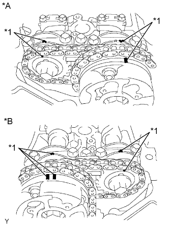
| 16. SET NO. 1 CYLINDER TO TDC/COMPRESSION |
Turn the crankshaft pulley and align its groove with the "0" timing mark of the timing chain cover.
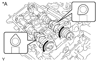
Check that the timing marks of the camshaft timing gears are aligned with the timing marks of the bearing cap as shown in the illustration.
Text in Illustration*A
| for Bank 1
|
*B
| for Bank 2
|
*1
| Timing Mark
|
If not, turn the crankshaft 1 complete revolution (360°) and align the timing marks as above.
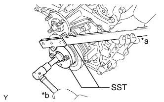
| 17. REMOVE CRANKSHAFT PULLEY |
Using SST, hold the crankshaft pulley and loosen the pulley bolt. Continue to loosen the bolt until only 2 or 3 threads are screwed into the crankshaft.
- SST
- 09213-54015(91651-60855)
09330-00021
Text in Illustration*a
| Hold
|
*b
| Loosen
|
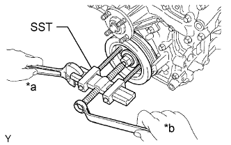
Using the pulley set bolt and SST, remove the crankshaft pulley and pulley bolt.
- SST
- 09950-50013(09951-05010,09952-05010,09953-05020,09954-05031)
Text in Illustration*a
| Hold
|
*b
| Loosen
|
| 18. REMOVE OIL PAN DRAIN PLUG |
Remove the oil pan drain plug and gasket.
| 19. REMOVE NO. 2 OIL PAN SUB-ASSEMBLY |
Remove the 14 bolts and 2 nuts.
Text in Illustration
| Bolt
|
| Nut
|
Insert the blade of an oil pan seal cutter between the oil pans. Cut through the applied sealer and remove the No. 2 oil pan.
- NOTICE:
- Be careful not to damage the contact surfaces of the oil pan and No. 2 oil pan.
- Be careful not to damage the No. 2 oil pan flange.
| 20. REMOVE OIL STRAINER SUB-ASSEMBLY |
Remove the bolt, 2 nuts, oil strainer and gasket.
| 21. REMOVE OIL PAN SUB-ASSEMBLY |
Remove the 17 bolts and 2 nuts.
Text in Illustration
| Bolt
|
| Nut
|
Using a screwdriver, remove the oil pan by prying between the oil pan and cylinder block as shown in the illustration.
- NOTICE:
- Be careful not to damage the contact surfaces of the cylinder block and oil pan.
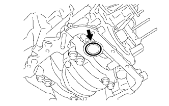
Remove the O-ring from the timing chain cover.
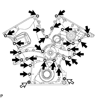
| 22. REMOVE TIMING CHAIN COVER SUB-ASSEMBLY |
Remove the 24 bolts and 2 nuts.
Text in Illustration
| Bolt
|
| Nut
|
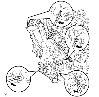
Remove the timing chain cover by prying between the timing chain cover and cylinder head or cylinder block with a screwdriver.
- NOTICE:
- Be careful not to damage the contact surfaces of the timing chain cover, cylinder block and cylinder head.
- HINT:
- Tape the screwdriver tip before use.
Remove the O-ring from the cylinder head for bank 2.
| 23. REMOVE ENGINE WATER PUMP ASSEMBLY |
Remove the 8 bolts, engine water pump and gasket.
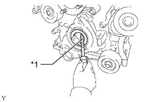
| 24. REMOVE FRONT CRANKSHAFT OIL SEAL |
Using a screwdriver, pry out the front crankshaft oil seal.
Text in Illustration*1
| Protective Tape
|
- NOTICE:
- Do not damage the surface of the oil seal press fit hole or crankshaft.
- HINT:
- Tape the screwdriver tip before use.
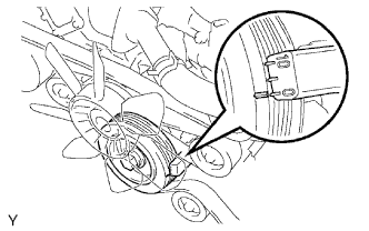
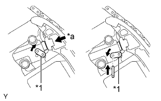
| 25. REMOVE NO. 1 CHAIN TENSIONER ASSEMBLY |
- NOTICE:
- Never rotate the crankshaft with the chain tensioner removed.
- Before rotating the camshaft with the timing chain removed, rotate the crankshaft counterclockwise 40° from TDC first.
While rotating the stopper plate of the tensioner upward, push in the plunger of the chain tensioner as shown in the illustration.
Text in Illustration*1
| Stopper Plate
|
*a
| Push
|
While rotating the stopper plate of the tensioner downward, insert a bar with a diameter of 3.5 mm (0.138 in.) into the holes in the stopper plate and tensioner to fix the stopper plate in place.
Remove the 2 bolts and No. 1 chain tensioner.
| 26. REMOVE CHAIN TENSIONER SLIPPER |
| 27. REMOVE NO. 1 IDLE GEAR SHAFT |
Using a 10 mm hexagon wrench, remove the No. 2 idle gear shaft, No. 1 idle gear and No. 1 idle gear shaft.
| 28. REMOVE NO. 2 CHAIN VIBRATION DAMPER |
Remove the 2 No. 2 chain vibration dampers.
| 29. REMOVE CHAIN SUB-ASSEMBLY |
| 30. REMOVE CRANKSHAFT TIMING GEAR OR SPROCKET |
Remove the crankshaft timing gear or sprocket.
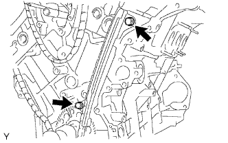
| 31. REMOVE NO. 1 CHAIN VIBRATION DAMPER |
Remove the 2 bolts and No. 1 chain vibration damper.
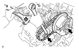
| 32. REMOVE CAMSHAFT TIMING GEARS AND NO. 2 CHAIN (for Bank 1) |
While raising up the No. 2 chain tensioner, insert a pin with a diameter of 1.0 mm (0.0394 in.) into the hole to fix the tensioner in place.
Text in Illustration*a
| Raise
|
Hold the hexagonal portion of the camshaft with a wrench and then remove the 2 bolts, the camshaft timing gear, the camshaft timing gear or sprocket and the No. 2 chain.
Text in Illustration*a
| Hold
|
*b
| Loosen
|
- NOTICE:
- Be careful not to damage the cylinder head and valve lifter with the wrench.
- Do not disassemble the camshaft timing gear.
| 33. REMOVE NO. 2 CHAIN TENSIONER ASSEMBLY |
Remove the bolt and No. 2 chain tensioner.
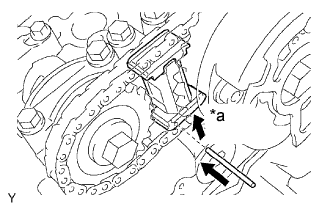
| 34. REMOVE CAMSHAFT TIMING GEARS AND NO. 2 CHAIN (for Bank 2) |
While pushing down the No. 3 chain tensioner, insert a pin with a diameter of 1.0 mm (0.0394 in.) into the hole to fix the tensioner in place.
Text in Illustration*a
| Push
|
Hold the hexagonal portion of the camshaft with a wrench and then remove the 2 bolts, the camshaft timing gear, the camshaft timing gear or sprocket and the No. 2 chain.
Text in Illustration*a
| Hold
|
*b
| Loosen
|
- NOTICE:
- Be careful not to damage the cylinder head and valve lifter with the wrench.
- Do not disassemble the camshaft timing gear.
| 35. REMOVE NO. 3 CHAIN TENSIONER ASSEMBLY |
Remove the bolt and No. 3 chain tensioner.
| 36. REMOVE CAMSHAFT AND NO. 2 CAMSHAFT |
- NOTICE:
- As the thrust clearance of the camshaft is small, the camshaft must be kept level while it is being removed. If the camshaft is not kept level, the portion of the cylinder head which received the shaft thrust may crack or be damaged, causing the camshaft to seize or break. To avoid this, the following steps should be carried out.
Remove the camshaft and No. 2 camshaft.
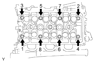
Rotate the camshafts counterclockwise using the hexagonal portion of each camshaft so that the cam lobes of the No. 1 cylinder are oriented as shown in the illustration.
Text in Illustration*A
| for Bank 1
|
Uniformly loosen and remove the 16 bearing cap bolts in the sequence shown in the illustration.
Text in Illustration*A
| for Bank 1
|
Remove the 8 bearing caps and 2 camshafts.
| 37. REMOVE NO. 1 CAMSHAFT BEARING |
| 38. REMOVE NO. 2 CAMSHAFT BEARING |
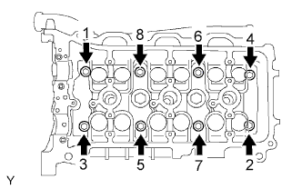
| 39. REMOVE NO. 3 CAMSHAFT SUB-ASSEMBLY AND NO. 4 CAMSHAFT SUB-ASSEMBLY |
Remove the No. 3 camshaft and No. 4 camshaft.
Uniformly loosen and remove the 16 bearing cap bolts in the sequence shown in the illustration.
Text in Illustration*A
| for Bank 2
|
Remove the 8 bearing caps and 2 camshafts.
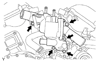
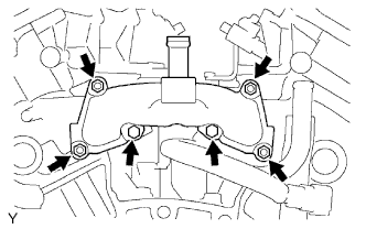
| 40. REMOVE REAR WATER BY-PASS JOINT |
Remove the 2 bolts, 4 nuts, rear water by-pass joint and 2 gaskets.
Remove the O-ring from the No. 1 water outlet pipe.
| 41. REMOVE CYLINDER HEAD LH |
Uniformly loosen and remove the 2 cylinder head bolts in the sequence shown in the illustration.
Using a 10 mm bi-hexagon wrench, uniformly loosen the 8 cylinder head bolts in the sequence shown in the illustration. Remove the 8 cylinder head bolts and plate washers.
- NOTICE:
- Be careful not to drop the plate washers into the cylinder head LH.
- Cylinder head warpage or cracking could result from removing bolts in the incorrect order.
Lift the cylinder head from the dowels on the cylinder block and place the cylinder head LH on wooden blocks on a bench.
- NOTICE:
- Be careful not to damage the contact surfaces of the cylinder head LH and cylinder block.
- HINT:
- If the cylinder head LH is difficult to lift off, pry between the cylinder head LH and cylinder block with a screwdriver.
| 42. REMOVE CYLINDER HEAD SUB-ASSEMBLY |
Using a 10 mm bi-hexagon wrench, uniformly loosen the 8 cylinder head bolts in the sequence shown in the illustration. Remove the 8 cylinder head bolts and plate washers.
- NOTICE:
- Be careful not to drop the plate washers into the cylinder head.
- Cylinder head warpage or cracking could result from removing bolts in the incorrect order.
Lift the cylinder head from the dowels on the cylinder block and place the cylinder head on wooden blocks on a bench.
- NOTICE:
- Be careful not to damage the contact surfaces of the cylinder head and cylinder block.
- HINT:
- If the cylinder head is difficult to lift off, pry between the cylinder head and cylinder block with a screwdriver.
| 43. REMOVE CYLINDER HEAD GASKET |
| 44. REMOVE NO. 2 CYLINDER HEAD GASKET |
| 45. REMOVE NO. 1 WATER OUTLET PIPE |
Disconnect the knock control sensor wire.
for Type A:
Remove the 3 bolts and No. 1 water outlet pipe.
for Type B:
Remove the bolt, 2 nuts and No. 1 water outlet pipe.
Disconnect the 2 knock sensor connectors.
Remove the 2 bolts and 2 knock sensors.
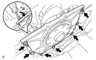
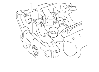
| 47. REMOVE REAR ENGINE OIL SEAL RETAINER |
Remove the 5 bolts and 2 nuts.
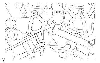
Using a screwdriver, remove the rear engine oil seal retainer by prying between the rear engine oil seal retainer and crankshaft bearing cap.
Text in Illustration*a
| Pry
|
- HINT:
- Tape the screwdriver tip before use.
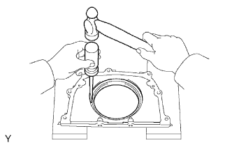
| 48. REMOVE REAR CRANKSHAFT OIL SEAL |
Using a screwdriver and hammer, tap out the rear engine oil seal.
- NOTICE:
- Be careful not to damage the rear engine oil seal retainer.
Remove the 24 valve lifters.
- HINT:
- Arrange the valve lifters in the correct order.