Engine Assembly -- Installation |
| 1. INSTALL ENGINE HANGER |
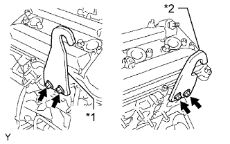
Install the 2 engine hangers with 4 bolts as shown in the illustration.
- Torque:
- 33 N*m{337 kgf*cm, 24 ft.*lbf}
Text in Illustration *1 No. 1 Engine Hanger *2 No. 2 Engine Hanger - HINT:
No. 1 Engine Hanger 12281-31060 No. 2 Engine Hanger 12282-31040 Bolt 90119-08A87
 |
| 2. REMOVE ENGINE FROM ENGINE STAND |
Attach an engine sling device and hang the engine with a chain block
Lift the engine and remove it from the engine stand.
- NOTICE:
- With the exception of installing the engine assembly to an engine stand or removing the engine assembly from an engine stand, do not perform any work on the engine while it is suspended, as doing so is dangerous.
- Pay attention to the angle of the sling device as the engine assembly or engine hangers may be damaged or deformed if the angle is incorrect.
| 3. INSTALL ENGINE ASSEMBLY |
Slowly lower the engine into the engine compartment.
Install the engine mounting brackets to the frame with the 4 bolts and 4 nuts.
- Torque:
- 38 N*m{387 kgf*cm, 28 ft.*lbf}
Remove the 2 engine hangers and 4 bolts.
| 4. INSTALL DRIVE PLATE AND RING GEAR SUB-ASSEMBLY |
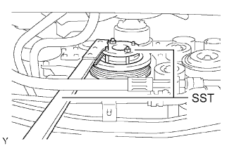
Using SST, hold the crankshaft.
- SST
- 09213-54015(91651-60855)
09330-00021
 |
Install the front spacer, drive plate and ring gear and rear spacer to the crankshaft.
Text in Illustration *1 Front Spacer *2 Drive Plate and Ring Gear *3 Rear Spacer 
Automatic Transmission Side - HINT:
- As the front spacer, drive plate and ring gear and rear spacer are not reversible, be sure to install them in the direction shown in the illustration.
 |
Clean the bolts and bolt holes.
Apply adhesive to 2 or 3 threads at the ends of the new bolts.
- Adhesive:
- Toyota Genuine Adhesive 1324, Three Bond 1324 or equivalent
Text in Illustration *1 Adhesive
 |
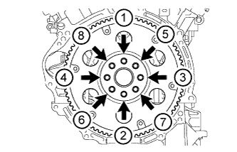
Uniformly install and tighten the 8 bolts in several steps in the sequence shown in the illustration.
- Torque:
- 83 N*m{846 kgf*cm, 61 ft.*lbf}
- NOTICE:
- Do not start the engine for at least 1 hour after installation.
 |
| 5. INSTALL REAR NO. 1 ENGINE MOUNTING INSULATOR |
Install the rear No. 1 engine mounting insulator to the automatic transmission with the 4 bolts.
- Torque:
- 47 N*m{479 kgf*cm, 35 ft.*lbf}
| 6. INSTALL AUTOMATIC TRANSMISSION ASSEMBLY |
| 7. INSTALL STARTER ASSEMBLY |
Install the starter with the 2 bolts.
- Torque:
- 58 N*m{591 kgf*cm, 43 ft.*lbf}
Connect the wire harness with the bolt.
- Torque:
- 20 N*m{202 kgf*cm, 15 ft.*lbf}
Connect the starter wire with the nut.
- Torque:
- 9.8 N*m{100 kgf*cm, 87 in.*lbf}
Connect the terminal cap.
Connect the starter connector.
| 8. INSTALL EXHAUST MANIFOLD SUB-ASSEMBLY LH |
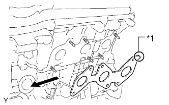
Install a new gasket to the cylinder head LH with the oval shape facing rearward.
Text in Illustration *1 Oval Shape Forward - NOTICE:
- Make sure the gasket is installed facing the proper direction.
 |
Install the exhaust manifold with 6 new nuts.
- Torque:
- 21 N*m{214 kgf*cm, 15 ft.*lbf}
Connect the air fuel ratio sensor connector.
| 9. INSTALL NO. 2 MANIFOLD STAY |
Install the No. 2 manifold stay with the 3 bolts.
- Torque:
- 40 N*m{408 kgf*cm, 30 ft.*lbf}
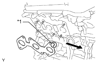
| 10. INSTALL EXHAUST MANIFOLD SUB-ASSEMBLY RH |
Install a new gasket to the cylinder head RH with the oval shape facing forward.
Text in Illustration *1 Oval Shape Forward - NOTICE:
- Make sure the gasket is installed facing the proper direction.
 |
Install the exhaust manifold with 6 new nuts.
- Torque:
- 21 N*m{214 kgf*cm, 15 ft.*lbf}
Connect the air fuel ratio sensor connector.
| 11. INSTALL MANIFOLD STAY |
Install the manifold stay with the 3 bolts.
- Torque:
- 40 N*m{408 kgf*cm, 30 ft.*lbf}
| 12. INSTALL FRONT FENDER APRON SEAL UPPER |
Install the RH and LH fender apron seals with the 10 clips.
| 13. INSTALL FRONT FENDER SEAL |
Install the RH and LH fender seals with the 10 clips.
| 14. INSTALL FRONT EXHAUST PIPE ASSEMBLY |
Connect the front exhaust pipe to the exhaust pipe support.
Install a new gasket to the end of the front exhaust pipe that connects to the exhaust manifold.
- NOTICE:
- Do not reuse the gasket.
Connect the front exhaust pipe to the exhaust manifold with the 2 nuts.
- Torque:
- 54 N*m{554 kgf*cm, 40 ft.*lbf}
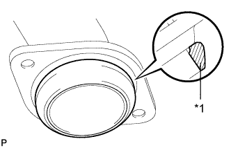
Using a vernier caliper, measure the free length of the compression spring.
- Minimum length:
- 40.5 mm (1.59 in.)
 |
Install a new gasket to the end of the front exhaust pipe that connects to the center exhaust pipe.
Text in Illustration *1 Gasket - NOTICE:
- Be sure to install the gasket so that it faces the correct direction.
- Do not reuse the gasket.
- When connecting the exhaust pipe, do not push in the gasket with the exhaust pipe.
- HINT:
- Using a plastic-faced hammer, uniformly tap the gasket so that the gasket and front exhaust pipe fit properly.
 |
Connect the front exhaust pipe to the center exhaust pipe and 2 compression springs with the 2 bolts.
- Torque:
- 43 N*m{438 kgf*cm, 32 ft.*lbf}
| 15. INSTALL FRONT NO. 2 EXHAUST PIPE ASSEMBLY |
Connect the front No. 2 exhaust pipe to the exhaust pipe support.
Install 2 new gaskets.
- NOTICE:
- Do not reuse the gaskets.
Install the front No. 2 exhaust pipe with 2 new nuts to the exhaust manifold.
- Torque:
- 54 N*m{554 kgf*cm, 40 ft.*lbf}
Connect the front No. 2 exhaust pipe with the 2 bolts and 2 new nuts to the front No. 2 exhaust pipe.
- Torque:
- 48 N*m{489 kgf*cm, 35 ft.*lbf}
| 16. INSTALL BATTERY |
| 17. INSTALL NO. 2 ENGINE WIRE |
Connect the No. 2 engine wire to the cylinder block with the bolt.
- Torque:
- 13 N*m{133 kgf*cm, 10 ft.*lbf}
| 18. INSTALL ENGINE WIRE |
Connect the 2 engine room junction block connectors and attach the wire clamp.
Connect the cable to the engine room junction block with the nut.
- Torque:
- 13 N*m{133 kgf*cm, 10 ft.*lbf}
Attach the 4 claws to install the side relay block cover.
Install the upper relay block cover.
Connect the ground wire with the bolt and clamp.
- Torque:
- 13 N*m{133 kgf*cm, 10 ft.*lbf}
Text in Illustration *a Frame Side
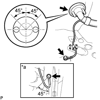 |
Connect the ground wire to the frame with the bolt so that it is within the range shown in the illustration.
- Torque:
- 13 N*m{133 kgf*cm, 10 ft.*lbf}
Push the engine wire through the dash panel into the cabin. The wire should be within the range shown in the illustration.
Connect the differential actuator connector.
Connect the ECM connectors.
Connect the 4 ECM connectors.
Connect the 4 wheel drive control ECU connector.
Install the glove compartment door (HILUX_TGN26 RM000003O2K00IX_01_0006.html).
Attach the wire clamp to the front No. 1 engine mounting bracket LH with the bolt.
- Torque:
- 13 N*m{128 kgf*cm, 9 ft.*lbf}
| 19. INSTALL INTAKE AIR SURGE TANK |
- NOTICE:
- Do not apply oil to the bolts and nuts listed below: :
Oil Application Prohibited Bolts for surge tank and intake manifold Nuts for surge tank and intake manifold
Install a new gasket to the intake air surge tank.
Using an 8 mm hexagon wrench, install the intake air surge tank with the 4 bolts and 2 nuts. Tighten the bolts and nuts in the order shown in the illustration.
- Torque:
- 28 N*m{286 kgf*cm, 21 ft.*lbf}
Text in Illustration Bolt 
Nut
 |
Install the water hose sub-assembly to the intake air surge tank with the 2 bolts.
- Torque:
- 5.4 N*m{55 kgf*cm, 48 in.*lbf}
Install the No. 2 surge tank stay with the 2 bolts.
- Torque:
- 21 N*m{214 kgf*cm, 15 ft.*lbf}
Install the No. 1 surge tank stay with the 2 bolts.
- Torque:
- 21 N*m{214 kgf*cm, 15 ft.*lbf}
Install the oil baffle plate with the bolt.
- Torque:
- 9.0 N*m{92 kgf*cm, 80 in.*lbf}
Install the throttle body bracket with the 2 bolts.
- Torque:
- 21 N*m{214 kgf*cm, 15 ft.*lbf}
Attach the 3 wire harness clamps and disconnect the wire harness.
Connect the throttle body connector.
Connect the vacuum switching valve (for ACIS) connector.
Connect the purge VSV connector.
Connect the No. 1 PCV hose.
Connect the vacuum hose.
Connect the purge line hose.
Connect the No. 5 water by-pass hose.
Connect the No. 4 water by-pass hose.
| 20. INSTALL HEATER WATER HOSE |
Connect the heater water inlet hose.
Connect the heater water outlet hose.
| 21. CONNECT NO. 2 FUEL PIPE SUB-ASSEMBLY |
Connect the No. 2 fuel pipe sub-assembly (HILUX_TGN26 RM000000YL401PX.html).
| 22. CONNECT NO. 1 FUEL PIPE SUB-ASSEMBLY |
Connect the No. 1 fuel pipe sub-assembly (HILUX_TGN26 RM000000YL401PX.html).
| 23. CONNECT COOLER COMPRESSOR ASSEMBLY |
Temporarily install the compressor with the bolt labeled A.
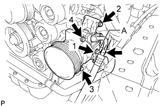 |
Install the compressor completely by tightening the 4 bolts in the order shown in the illustration.
- Torque:
- 25 N*m{250 kgf*cm, 18 ft.*lbf}
- NOTICE:
- In order to prevent misalignment, which causes belt rattle, tightening of the bolts must be performed in the order shown.
Connect the compressor connector.
Connect the suction hose with the 2 bolts.
- Torque:
- 5.4 N*m{55 kgf*cm, 48 in.*lbf}
| 24. INSTALL VANE PUMP ASSEMBLY |
Install the vane pump with the 2 bolts.
- Torque:
- 21 N*m{214 kgf*cm, 15 ft.*lbf}
- NOTICE:
- Do not hit other parts with the pulley when installing the vane pump.
Connect the power steering oil pressure switch connector.
| 25. INSTALL RADIATOR ASSEMBLY |
Install the radiator with the 4 bolts.
- Torque:
- 12 N*m{122 kgf*cm, 9 ft.*lbf}
Attach the 4 clamps of the 2 front airbag sensors to the radiator.
Connect the 2 front airbag sensor front connectors.
| 26. INSTALL FAN SHROUD |
Install the fan pulley to the water pump.
Place the shroud together with the coupling fan between the radiator and engine.
- NOTICE:
- Be careful not to damage the radiator core.
Install the fluid coupling fan to the water pump with the 4 nuts. Tighten the nuts as much as possible by hand.
Attach the shroud's claws to the radiator as shown in the illustration.
 |
Install the shroud with the 2 bolts.
- Torque:
- 5.0 N*m{51 kgf*cm, 44 in.*lbf}
Connect the reservoir hose to the radiator tank upper.
Install the fan and generator V belt (HILUX_TGN26 RM000000YN200BX_01_0001.html).
Tighten the 4 nuts of the fluid coupling fan.
- Torque:
- 21 N*m{214 kgf*cm, 15 ft.*lbf}
Install the oil reservoir with the 3 bolts.
- Torque:
- 5.0 N*m{46 kgf*cm, 40 in.*lbf}
| 27. CONNECT OIL COOLER INLET HOSE |
Connect the oil cooler inlet hose to the radiator tank lower.
| 28. CONNECT OIL COOLER OUTLET HOSE |
Connect the oil cooler outlet hose to the radiator tank lower.
| 29. CONNECT RADIATOR HOSE INLET |
| 30. CONNECT RADIATOR HOSE OUTLET |
| 31. INSTALL RADIATOR SIDE DEFLECTOR RH |
Install the deflector with the 2 clips and attach the claw.
| 32. INSTALL RADIATOR SIDE DEFLECTOR LH |
Install the deflector with the 2 clips and attach the claw.
| 33. INSTALL NO. 2 AIR CLEANER HOSE |
Install the No. 2 air cleaner hose with the 2 bolts.
- Torque:
- 14 N*m{143 kgf*cm, 10 ft.*lbf}
| 34. INSTALL AIR CLEANER ASSEMBLY |
Install the air cleaner with the 2 bolts.
- Torque:
- 8.0 N*m{82 kgf*cm, 71 in.*lbf}
Tighten the 2 hose clamps.
Attach the 2 wire harness clamps.
Connect the mass air flow meter connector.
Connect the vacuum hose.
| 35. INSTALL RADIATOR GRILLE |
Attach the 6 claws to install the radiator grille.
Install the 2 screws and 2 clips.
| 36. CONNECT NO. 2 PCV HOSE |
Connect the No. 2 PCV hose and clamp.
| 37. INSTALL HOOD SUB-ASSEMBLY |
Install the hood with the 4 bolts and adjust the hood to the correct position.
- Torque:
- 13 N*m{133 kgf*cm, 10 ft.*lbf}
Connect the washer nozzle hose.
| 38. CONNECT CABLE TO NEGATIVE BATTERY TERMINAL |
- NOTICE:
- When disconnecting the cable, some systems need to be initialized after the cable is reconnected (HILUX_TGN26 RM000004QR3009X.html).
| 39. ADD ENGINE OIL |
Add fresh engine oil.
- Standard Oil Grade:
Oil Grade Oil Viscosity (SAE) API grade SL "Energy-Conserving", SM "Energy-Conserving", SN "Resource-Conserving" or ILSAC multigrade engine oil 5W-30
10W-30
(5W-30 is the best choice for good fuel economy and good starting in cold weather)API grade SL, SM or SN multigrade engine oil 15W-40
20W-50
- Standard Oil Capacity:
Item Specified Condition Drain and refill without oil filter change 5.2 liters (5.5 US qts, 4.6 Imp. qts) Drain and refill with oil filter change 5.5 liters (5.8 US qts, 4.8 Imp. qts) Dry fill 6.6 liters (7.0 US qts, 5.8 Imp. qts)
Install the oil filler cap.
| 40. ADD ENGINE COOLANT |
Tighten the 2 cylinder block water drain cock plugs.
- Torque:
- 13 N*m{130 kgf*cm, 9 ft.*lbf}
Tighten the radiator drain cock plug by hand.
Add engine coolant.
- Standard capacity:
- 9.8 liters (10.4 US qts, 8.6 Imp. qts)
- NOTICE:
- Never use water as a substitute for engine coolant.
- HINT:
- TOYOTA vehicles are filled with TOYOTA SLLC at the factory. In order to avoid damage to the engine cooling system and other technical problems, only use TOYOTA SLLC or similar high quality ethylene glycol based non-silicate, non-amine, non-nitrite, non-borate coolant with long-life hybrid organic acid technology (coolant with long-life hybrid organic acid technology consists of a combination of low phosphates and organic acids).
- Press the radiator hose inlet and radiator hose outlet several times by hand, and then check the coolant level. If the coolant level is low, add coolant.
Slowly pour coolant into the radiator reservoir until it reaches the F line.
Install the reservoir cap.
Install the radiator cap.*1
Start the engine and stop it immediately.*2
Allow approximately 10 seconds to pass. Then remove the radiator cap and check the coolant level. If the coolant level has decreased, add coolant.*3
Repeat steps *1, *2 and *3 until the coolant level does not decrease.
- HINT:
- Be sure to perform this step while the engine is cold, as air in the radiator hose inlet will flow into the radiator if the engine is warmed up and the thermostat opens.
Install the radiator cap.*4
Set the air conditioning as follows.*5
Measurement Condition Item Condition Fan speed Any setting except off Temperature Toward WARM Air conditioning switch Off
Start the engine, warm it up until the thermostat opens, and then continue to run the engine for several minutes to circulate the coolant.*6
- CAUTION:
- Wear protective gloves. Hot areas on the parts may injure your hands.
- Be careful of the fan.
- Be careful as the engine, radiator and radiator hoses are hot and can cause burns.
- NOTICE:
- Immediately after starting the engine, if the radiator reservoir does not have any coolant, perform the following: 1) stop the engine, 2) wait until the coolant has cooled down, and 3) add coolant until the coolant is filled to the F line.
- Do not start the engine when there is no coolant in the radiator reservoir.
- Pay attention to the needle of the engine coolant temperature receiver gauge. Make sure that the needle does not show an abnormally high temperature.
- If there is not enough coolant, the engine may burn out or overheat.
- HINT:
- Press the radiator hose inlet and radiator hose outlet several times by hand to bleed air while warming up the engine.
- The thermostat opening timing can be confirmed by pressing the radiator hose outlet by hand and checking when the engine coolant starts to flow inside the hose.
Stop the engine and wait until the engine coolant cools down to ambient temperature. Then remove the radiator cap and check the coolant level.*7
- CAUTION:
- Do not remove the radiator cap while the engine and radiator are still hot. Pressurized, hot engine coolant and steam may be released and cause serious burns.
If the coolant level has decreased, add coolant and warm up the engine until the thermostat opens.*8
If the coolant level has not decreased, check that the coolant level in the radiator reservoir is at the F line.
If the coolant level is below the F line, repeat steps *4 through *8.
If the coolant level is above the F line, drain coolant until the coolant level reaches the F line.
| 41. INSPECT FOR COOLANT LEAK |
Remove the radiator cap.
- CAUTION:
- To avoid being burned, do not remove the radiator cap while the engine and radiator are still hot. Thermal expansion may cause hot engine coolant and steam to blow out from the radiator.
Fill the radiator with coolant and attach a radiator cap tester.
Warm up the engine.
Using the radiator cap tester, increase the pressure inside the radiator to 118 kPa (1.2 kgf/cm2, 17 psi), and then check that the pressure does not drop.
If the pressure drops, check the hose, radiator and water pump for leakage. If no external leakage is found, check the heater core, cylinder block and cylinder head.
Install the radiator cap.
| 42. INSPECT FOR FUEL LEAK |
Make sure that there are no fuel leaks after performing maintenance on the fuel system.
Connect the intelligent tester to the DLC3.
Turn the ignition switch to ON and turn the intelligent tester on.
- NOTICE:
- Do not start the engine.
Enter the following menus: Powertrain / Engine and ECT / Active Test / Control the Fuel Pump / Speed.
Check that there are no leaks from the fuel system.
If there are fuel leaks, repair or replace parts as necessary.Turn the ignition switch off.
Disconnect the intelligent tester from the DLC3.
| 43. INSPECT FOR OIL LEAK |
Start the engine. Make sure that there are no oil leaks from the area that was worked on.
| 44. INSPECT FOR EXHAUST GAS LEAK |
| 45. INSTALL V-BANK COVER |
Install the V-bank cover with the 2 nuts.
- Torque:
- 7.5 N*m{76 kgf*cm, 66 in.*lbf}
| 46. INSTALL NO. 2 ENGINE UNDER COVER |
Install the No. 2 engine under cover with the 4 bolts.
- Torque:
- 28 N*m{286 kgf*cm, 21 ft.*lbf}
| 47. INSTALL NO. 1 ENGINE UNDER COVER |
- Torque:
- 28 N*m{286 kgf*cm, 21 ft.*lbf}
| 48. INSTALL ENGINE SIDE COVER SUB-ASSEMBLY LH |
Install the engine side cover with the 3 bolts and 2 clips.
- Torque:
- 12 N*m{117 kgf*cm, 8 ft.*lbf}
| 49. INSTALL ENGINE SIDE COVER SUB-ASSEMBLY RH |
- HINT:
- Use the same procedure described for the LH side.
| 50. INSPECT IGNITION TIMING |
- NOTICE:
- Turn all electrical systems off.
Warm up the engine.
When using the intelligent tester:
Connect the intelligent tester to the DLC3.
Enter the following menus: Powertrain / Engine and ECT / Data List / All Data / IGN Advance.
Inspect the ignition timing during idling.
- Standard ignition timing:
- 7 to 24° BTDC @ idle (transmission in neutral and A/C switch off)
Check that the ignition timing advances immediately when the engine speed is increased.
When not using the intelligent tester:
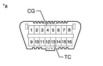
Using SST, connect terminals 13 (TC) and 4 (CG) of the DLC3.
- SST
- 09843-18040
Text in Illustration *a Front view of DLC3 - NOTICE:
- Be sure not to improperly connect the terminals. This may damage the engine.
Connect the tester probe of a timing light to the wire of the ignition coil connector for the No. 1 cylinder.
- NOTICE:
- Use a timing light that detects primary signals.
- After the inspection, be sure to wrap the wire harness with tape.
Inspect the ignition timing during idling.
- Standard ignition timing:
- 8 to 12° BTDC @ idle (transmission in neutral and A/C switch off)
Remove SST from the DLC3.
Inspect the ignition timing during idling.
- Standard ignition timing:
- 7 to 24° BTDC @ idle (transmission in neutral and A/C switch off)
Disconnect the timing light from the engine.
| 51. INSPECT ENGINE IDLE SPEED |
- NOTICE:
- Turn all the electrical systems off.
Warm up the engine.
When using the intelligent tester:
Connect the intelligent tester to the DLC3.
Enter the following menus: Powertrain / Engine and ECT / Data List / All Data / Engine Speed.
Inspect the engine idle speed.
- Standard idle speed:
- 650 to 750 rpm (transmission in neutral and A/C switch off)
When not using the intelligent tester:
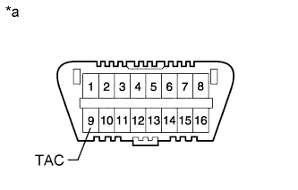
Connect SST to terminal 9 (TAC) of the DLC3.
- SST
- 09843-18030
Text in Illustration *a Front view of DLC3 Race the engine at 2500 rpm for approximately 90 seconds
Inspect the engine idle speed.
- Standard idle speed:
- 650 to 750 rpm (transmission in neutral and A/C switch off)
 |
| 52. INSPECT CO/HC |
- HINT:
- This check is to determine whether or not the idle CO/HC concentration complies with regulations.
Start the engine.
Run the engine at 2500 rpm for approximately 180 seconds.
Insert the CO/HC meter testing probe at least 40 cm (1.31 ft) into the tailpipe during idling.
Immediately check the CO/HC concentration during idling and/or at 2500 rpm.
- HINT:
- When carrying out the 2 tests (idling and 2500 rpm), the measurement orders are prescribed by the applicable local regulations.
If the CO/HC concentration does not comply with regulations, perform troubleshooting in the order given below.
Check the air fuel ratio sensor operation (HILUX_TGN26 RM000002RV201RX.html) and heated oxygen sensor operation (HILUX_TGN26 RM000002RV601FX.html).
Refer to the table below for possible causes, and then inspect and correct the corresponding causes if necessary.
CO HC Problem Possible Cause Normal High Rough idle 1. Faulty ignitions: - Incorrect timing
- Fouled, shorted or improperly gapped plugs
3. Leaky intake and exhaust valves
4. Leaky cylindersLow High Rough idle
(Fluctuating HC reading)1. Vacuum leaks: - PCV hose
- Intake manifold
- Throttle body
High High Rough idle
(Black smoke from exhaust)1. Restricted air filter
2. Plugged PCV valve
3. Faulty SFI system:- Faulty pressure regulator
- Defective engine coolant temperature sensor
- Faulty ECM
- Faulty injector
- Faulty throttle position sensor
- Faulty mass air flow sensor
- Incorrect timing