PRECAUTION
DISCONNECT CABLE FROM NEGATIVE BATTERY TERMINAL
REMOVE INTAKE AIR SURGE TANK
REMOVE IGNITION COIL ASSEMBLY
REMOVE CYLINDER HEAD COVER SUB-ASSEMBLY
REMOVE CYLINDER HEAD COVER SUB-ASSEMBLY LH
SET NO. 1 CYLINDER TO TDC/COMPRESSION
REMOVE NO. 1 CHAIN TENSIONER ASSEMBLY
REMOVE NO. 2 CAMSHAFT
REMOVE NO. 2 CHAIN TENSIONER ASSEMBLY
REMOVE CAMSHAFT
REMOVE NO. 4 CAMSHAFT SUB-ASSEMBLY
REMOVE NO. 3 CHAIN TENSIONER ASSEMBLY
REMOVE NO. 3 CAMSHAFT SUB-ASSEMBLY
- NOTICE:
- After turning the ignition switch off, waiting time may be required before disconnecting the cable from the battery terminal. Therefore, make sure to read the disconnecting the cable from the battery terminal notice before proceeding with work (HILUX_TGN26 RM000004QR1006X.html).
| 2. DISCONNECT CABLE FROM NEGATIVE BATTERY TERMINAL |
- NOTICE:
- When disconnecting the cable, some systems need to be initialized after the cable is reconnected (HILUX_TGN26 RM000004QR3009X.html).
| 3. REMOVE INTAKE AIR SURGE TANK |
(HILUX_TGN26 RM000002I4V00CX.html)
| 4. REMOVE IGNITION COIL ASSEMBLY |
Disconnect the 6 ignition coil connectors.
Remove the 6 bolts and 6 ignition coils.
| 5. REMOVE CYLINDER HEAD COVER SUB-ASSEMBLY |
Remove the 10 bolts, 3 seal washers, 2 nuts, cylinder head cover and gasket.
Text in Illustration
| Bolt
|

| Nut
|
| 6. REMOVE CYLINDER HEAD COVER SUB-ASSEMBLY LH |
Remove the 10 bolts, 3 seal washers, 2 nuts, cylinder head cover and gasket.
Text in Illustration
| Bolt
|
| Nut
|
| 7. SET NO. 1 CYLINDER TO TDC/COMPRESSION |
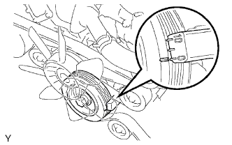
Turn the crankshaft pulley, and align the notch with timing mark 0 of the timing chain cover.
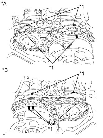
Check that the timing marks of the camshaft timing gears are aligned with the timing marks of the bearing cap as shown in the illustration.
If the timing marks are not aligned, turn the crankshaft 1 complete revolution (360°) and align the timing marks as described above.
Text in Illustration*A
| for Bank 1
|
*B
| for Bank 2
|
*1
| Timing Mark
|
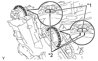
Place paint marks on the No. 1 chain links that correspond with the timing marks of the camshaft timing gears.
Text in Illustration*1
| Paint Mark
|
*2
| Timing Mark
|
| 8. REMOVE NO. 1 CHAIN TENSIONER ASSEMBLY |
- NOTICE:
- Never rotate the crankshaft with the chain tensioner removed.
- Before rotating the camshaft with the timing chain removed, rotate the crankshaft counterclockwise 40° from TDC first.
Remove the 4 bolts, timing chain cover plate and gasket.
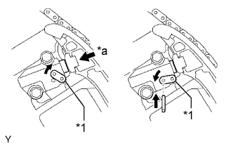
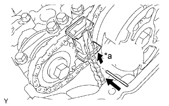
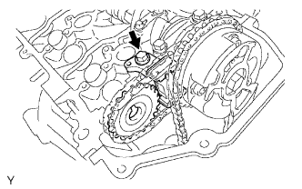
While turning the stopper plate of the tensioner clockwise, push in the plunger of the No. 1 chain tensioner as shown in the illustration.
Text in Illustration*1
| Stopper Plate
|
*a
| Push
|
While turning the stopper plate of the tensioner counterclockwise, insert a bar with a diameter of 3.5 mm (0.138 in.) into the holes in the stopper plate and tensioner to fix the stopper plate in place.
Remove the 2 bolts and No. 1 chain tensioner.
- NOTICE:
- As the thrust clearance of the camshaft is small, the camshaft must be kept level while it is being removed. If the camshaft is not kept level, the portion of the cylinder head which receives the shaft thrust may crack or be damaged, causing the camshaft to seize or break. To avoid this, the following steps should be carried out.
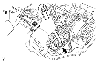
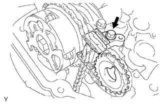
While raising the No. 2 chain tensioner, insert a pin with a diameter of 1.0 mm (0.0394 in.) into the hole to fix the tensioner in place.
Text in Illustration*a
| Raise
|
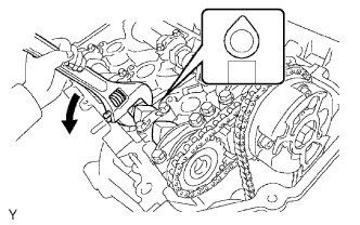
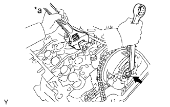
Hold the hexagonal portion of the No. 2 camshaft with a wrench and remove the camshaft timing sprocket set bolt.
Text in Illustration*a
| Hold
|
- NOTICE:
- Be careful not to damage the cylinder head and valve lifter with the wrench.
Separate the camshaft timing sprocket from the No. 2 camshaft.
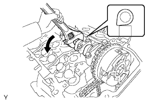
Rotate the camshaft counterclockwise using a wrench so that the cam lobes of the No. 1 cylinder face upward as shown in the illustration.
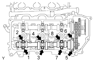
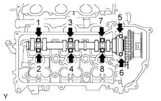
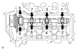
Using several steps, loosen and remove the 8 bearing cap bolts uniformly in the sequence shown in the illustration.
Remove the 4 bearing caps and No. 2 camshaft.
| 10. REMOVE NO. 2 CHAIN TENSIONER ASSEMBLY |
Remove the No. 2 chain tensioner bolt, and then remove the No. 2 chain tensioner and camshaft timing sprocket.
- NOTICE:
- As the thrust clearance of the camshaft is small, the camshaft must be kept level while it is being removed. If the camshaft is not kept level, the portion of the cylinder head which receives the shaft thrust may crack or be damaged, causing the camshaft to seize or break. To avoid this, the following steps should be carried out.
Hold the hexagonal portion of the camshaft with a wrench and loosen the camshaft timing gear set bolt.
Text in Illustration*a
| Hold
|
- NOTICE:
- Be careful not to damage the cylinder head and valve lifter with the wrench.
- Do not disassemble the camshaft timing gear assembly.
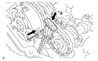
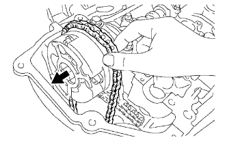
Slide the camshaft timing gear and separate the chain from the camshaft timing gear.
Text in Illustration
| Slide
|
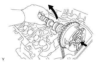
Rotate the camshaft counterclockwise using a wrench so that the cam lobes of the No. 1 cylinder face downward as shown in the illustration.
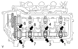
Using several steps, loosen and remove the 8 bearing cap bolts in the sequence shown in the illustration.
Remove the 4 bearing caps.
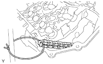
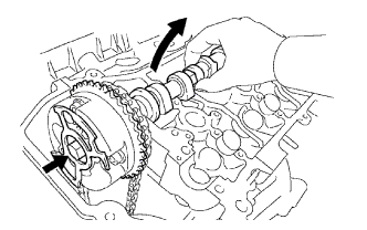
Remove the camshaft timing gear set bolt with the camshaft lifted up, and then remove the camshaft and camshaft timing gear together with the No. 2 chain.
Tie the chain with a string as shown in the illustration.
- NOTICE:
- Be careful not to drop anything inside the timing chain cover.
| 12. REMOVE NO. 4 CAMSHAFT SUB-ASSEMBLY |
- NOTICE:
- As the thrust clearance of the camshaft is small, the camshaft must be kept level while it is being removed. If the camshaft is not kept level, the portion of the cylinder head which receives the shaft thrust may crack or be damaged, causing the camshaft to seize or break. To avoid this, the following steps should be carried out.
While pushing down the No. 3 chain tensioner, insert a pin with a diameter of 1.0 mm (0.0394 in.) into the hole to fix the tensioner in place.
Text in Illustration*a
| Push
|
Hold the hexagonal portion of the No. 4 camshaft with a wrench and remove the camshaft timing sprocket set bolt.
- NOTICE:
- Be careful not to damage the cylinder head and valve lifter with the wrench.
Separate the camshaft timing sprocket from the No. 4 camshaft.
Using several steps, loosen and remove the 8 bearing cap bolts uniformly in the sequence shown in the illustration.
Remove the 4 bearing caps and No. 4 camshaft.
| 13. REMOVE NO. 3 CHAIN TENSIONER ASSEMBLY |
Remove the No. 3 chain tensioner bolt, and then remove the No. 3 chain tensioner and camshaft timing sprocket.
| 14. REMOVE NO. 3 CAMSHAFT SUB-ASSEMBLY |
- NOTICE:
- As the thrust clearance of the camshaft is small, the camshaft must be kept level while it is being removed. If the camshaft is not kept level, the portion of the cylinder head which receives the shaft thrust may crack or be damaged, causing the camshaft to seize or break. To avoid this, the following steps should be carried out.
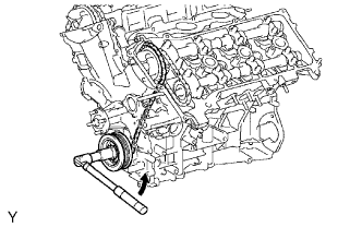
Release the chain tension between the camshaft timing gear (LH bank) and crankshaft timing gear by turning the crankshaft pulley counterclockwise slightly.
Text in Illustration
| Slightly Turn
|
Hold the hexagonal portion of the No. 3 camshaft with a wrench and loosen the camshaft timing gear set bolt.
- NOTICE:
- Be careful not to damage the cylinder head and valve lifter with the wrench.
- Do not disassemble the camshaft timing gear assembly.
Slide the camshaft timing gear and separate the chain from the camshaft timing gear.
Text in Illustration
| Slide
|
Using several steps, loosen and remove the 8 bearing cap bolts uniformly in the sequence shown in the illustration.
Remove the 4 bearing caps.
Remove the camshaft timing gear set bolt with the No. 3 camshaft lifted up, and then remove the No. 3 camshaft and camshaft timing gear together with the No. 2 chain.
Tie the chain with a string as shown in the illustration.
- NOTICE:
- Be careful not to drop anything inside the timing chain cover.