Sfi System (W/O Secondary Air Injection System) Starter Signal Circuit
DESCRIPTION
WIRING DIAGRAM
INSPECTION PROCEDURE
READ VALUE USING INTELLIGENT TESTER (STARTER SIGNAL)
CHECK STARTER (ST) RELAY (POWER SOURCE)
INSPECT STARTER (ST) RELAY
CHECK HARNESS AND CONNECTOR (STARTER (ST) RELAY - BODY GROUND)
CHECK HARNESS AND CONNECTOR (STARTER (ST) RELAY - IGNITION SWITCH)
INSPECT IGNITION SWITCH ASSEMBLY
SFI SYSTEM (w/o Secondary Air Injection System) - Starter Signal Circuit |
DESCRIPTION
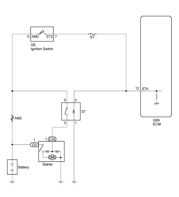
While the engine is being cranked, current flows from terminal ST1 of the ignition switch directly to terminal STA of the ECM (STA signal).
WIRING DIAGRAM
INSPECTION PROCEDURE
- NOTICE:
- Inspect the fuses for circuits related to this system before performing the following inspection procedure.
- HINT:
- This inspection procedure is based on the premise that the engine can crank normally. If the engine cannot crank normally, proceed to the problem symptoms table (HILUX_TGN26 RM000000PDG0LVX.html).
| 1.READ VALUE USING INTELLIGENT TESTER (STARTER SIGNAL) |
Connect the intelligent tester to the DLC3.
Turn the ignition switch to ON.
Turn the intelligent tester on.
Enter the following menus: Powertrain / Engine and ECT / Data List / Starter Signal.
Read the value.
- OK:
Ignition Switch Position
| Starter Signal
|
ON
| Close (Starter signal OFF)
|
START
| Open (Starter signal ON)
|
| 2.CHECK STARTER (ST) RELAY (POWER SOURCE) |
Remove the starter (ST) relay from the engine room relay block and junction block.
Measure the voltage according to the value(s) in the table below.
- Standard Voltage:
Tester Connection
| Condition
| Specified Condition
|
Starter (ST) relay terminal 2 - Body ground
| Engine cranking
| 11 to 14 V
|
- HINT:
- The engine does not crank because the relay is not installed.
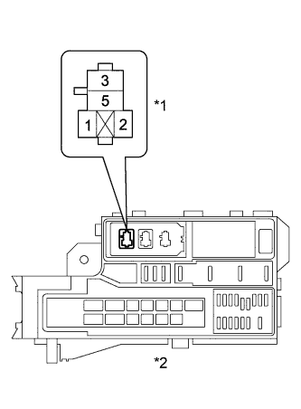
Text in Illustration*1
| Starter (ST) Relay
|
*2
| Engine Room Relay Block and Junction Block Assembly
|
| 3.INSPECT STARTER (ST) RELAY |
Inspect the starter (ST) relay (HILUX_TGN26 RM000000WPQ05MX_01_0001.html).
| | REPLACE STARTER (ST) RELAY |
|
|
| 4.CHECK HARNESS AND CONNECTOR (STARTER (ST) RELAY - BODY GROUND) |
Remove the starter (ST) relay from the engine room relay block and junction block.
Measure the resistance according to the value(s) in the table below.
- Standard Resistance:
Tester Connection
| Condition
| Specified Condition
|
Starter (ST) relay terminal 1 - Body ground
| Always
| Below 1 Ω
|
| | REPAIR OR REPLACE HARNESS OR CONNECTOR (STARTER (ST) RELAY - BODY GROUND) |
|
|
| OK |
|
|
|
| REPAIR OR REPLACE HARNESS OR CONNECTOR (ECM - IGNITION SWITCH) |
|
| 5.CHECK HARNESS AND CONNECTOR (STARTER (ST) RELAY - IGNITION SWITCH) |
Remove the starter (ST) relay from the engine room relay block and junction block.
Disconnect the ignition switch connector.
Measure the resistance according to the value(s) in the table below.
- Standard Resistance:
Tester Connection
| Condition
| Specified Condition
|
Starter (ST) relay terminal 2 - G9-7 (ST2)
| Always
| Below 1 Ω
|
Starter (ST) relay terminal 2 or G9-7 (ST2) - Body ground
| Always
| 10 kΩ or higher
|
| | REPAIR OR REPLACE HARNESS OR CONNECTOR (STARTER (ST) RELAY - IGNITION SWITCH) |
|
|
| 6.INSPECT IGNITION SWITCH ASSEMBLY |
Inspect the ignition switch assembly (HILUX_TGN26 RM00000135X01BX.html).
| OK |
|
|
|
| REPAIR OR REPLACE HARNESS OR CONNECTOR (IGNITION SWITCH - BATTERY) |
|