Sfi System (W/O Secondary Air Injection System) Ecm Back-Up Power Source Circuit
DESCRIPTION
WIRING DIAGRAM
INSPECTION PROCEDURE
CHECK HARNESS AND CONNECTOR (ECM - BATTERY)
INSPECT BATTERY
CHECK BATTERY TERMINAL
CHECK ECM (BATT VOLTAGE)
SFI SYSTEM (w/o Secondary Air Injection System) - ECM Back-up Power Source Circuit |
DESCRIPTION
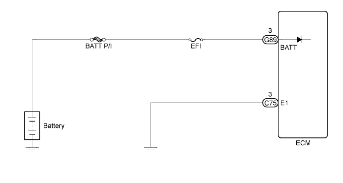
While the ignition switch is off, battery voltage is supplied to terminal BATT of the ECM for the DTC memory, air-fuel ratio adaptive control value memory, etc.
WIRING DIAGRAM
INSPECTION PROCEDURE
- NOTICE:
- Inspect the fuses for circuits related to this system before performing the following inspection procedure.
| 1.CHECK HARNESS AND CONNECTOR (ECM - BATTERY) |
Disconnect the ECM connector.
Disconnect the cable from the positive (+) battery terminal.
Measure the resistance according to the value(s) in the table below.
- Standard Resistance:
Tester Connection
| Condition
| Specified Condition
|
G89-3 (BATT) - Positive (+) battery cable terminal
| Always
| Below 1 Ω
|
G89-3 (BATT) or positive (+) battery cable terminal - Body ground
| Always
| 10 kΩ or higher
|
| | REPAIR OR REPLACE HARNESS OR CONNECTOR |
|
|
Check that the battery is not depleted (HILUX_TGN26 RM000000V4301SX.html).
- OK:
- Battery is not depleted.
Check that the battery terminals are not loose or corroded.
- OK:
- Battery terminals are not loose or corroded.
| 4.CHECK ECM (BATT VOLTAGE) |
Measure the voltage according to the value(s) in the table below.
- Standard Voltage:
Tester Connection
| Condition
| Specified Condition
|
G89-3 (BATT) - C75-3 (E1)
| Always
| 8 to 14 V
|
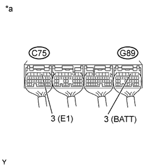
Text in Illustration*a
| Component with harness connected
(ECM)
|