READ VALUE USING INTELLIGENT TESTER (INTAKE AIR TEMPERATURE)
READ VALUE USING INTELLIGENT TESTER (CHECK FOR OPEN IN WIRE HARNESS)
CHECK HARNESS AND CONNECTOR (INTAKE AIR TEMPERATURE SENSOR - ECM)
READ VALUE USING INTELLIGENT TESTER (CHECK FOR SHORT IN WIRE HARNESS)
CHECK HARNESS AND CONNECTOR (INTAKE AIR TEMPERATURE SENSOR - ECM)
CONFIRM GOOD CONNECTION TO SENSOR. IF OK, REPLACE INTAKE AIR TEMPERATURE SENSOR
REPAIR OR REPLACE HARNESS OR CONNECTOR
CONFIRM GOOD CONNECTION TO ECM. IF OK, REPLACE ECM.
REPLACE INTAKE AIR TEMPERATURE SENSOR
CONFIRM WHETHER MALFUNCTION HAS BEEN SUCCESSFULLY REPAIRED
DTC P0110 Intake Air Temperature Circuit |
DTC P0112 Intake Air Temperature Circuit Low Input |
DTC P0113 Intake Air Temperature Circuit High Input |
DESCRIPTION
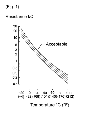
The intake air temperature sensor is built into the mass air flow meter and detects the intake air temperature.A thermistor built into the sensor changes its resistance value according to the intake air temperature.
The lower the intake air temperature, the higher the thermistor resistance value. The higher the intake air temperature, the lower the thermistor resistance value (See Fig. 1).
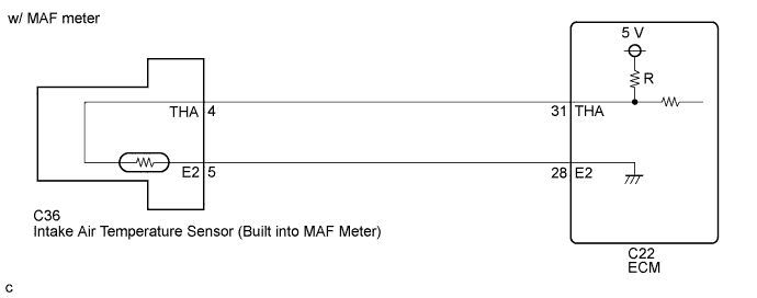
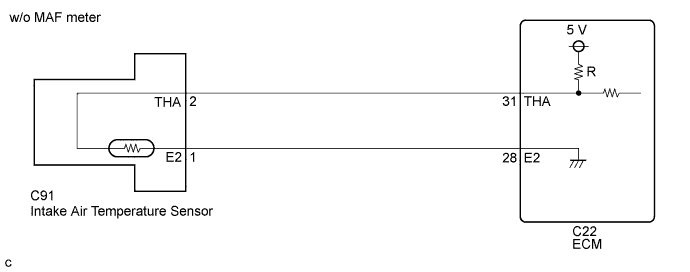
The intake air temperature sensor is connected to the ECM.
The 5 V power source voltage from the ECM is applied to the intake air temperature sensor from terminal THA via resistor R.
Resistor R and the intake air temperature sensor are connected in series. When the resistance value of the intake air temperature sensor changes in accordance with the intake air temperature, the voltage at terminal THA also changes. Based on this signal, the ECM increases the fuel injection volume to improve driveability with a cold engine.
| DTC Detection Drive Pattern | DTC Detection Condition | Trouble Area |
| Ignition switch to ON for 0.5 seconds | Open or short the IAT sensor for 0.5 seconds (1 trip detection logic). |
|
| DTC Detection Drive Pattern | DTC Detection Condition | Trouble Area |
| Ignition switch to ON for 0.5 seconds | Short in the IAT sensor for 0.5 seconds (1 trip detection logic). |
|
| DTC Detection Drive Pattern | DTC Detection Condition | Trouble Area |
| Ignition switch to ON for 0.5 seconds | Open in the IAT sensor for 0.5 seconds (1 trip detection logic). |
|
| DTC No. | Data List |
| P0110 | Intake Air |
| P0112 | |
| P0113 |
- HINT:
- If DTC P0110, P0112 and/or P0113 is stored, the following symptoms may appear:
- Misfire
- Combustion noise
- Black smoke
- White smoke
- Lack of power
- When DTC P0110, P0112 and/or P0113 is stored, check the intake air temperature by entering the following menus: Powertrain / Engine and ECT / Data List / Intake Air.
Reference Temperature Displayed Malfunction -40°C (-40°F) Open circuit 140°C (284°F) or higher Short circuit
WIRING DIAGRAM
INSPECTION PROCEDURE
- NOTICE:
- After replacing the ECM, the new ECM needs registration (HILUX_TGN26 RM0000012XK03ZX.html) and initialization (HILUX_TGN26 RM000000TIN04BX.html).
- HINT:
- Read freeze frame data using the intelligent tester. Freeze frame data records the engine condition when malfunctions are detected. When troubleshooting, freeze frame data can help determine if the vehicle was moving or stationary, if the engine was warmed up or not, and other data from the time the malfunction occurred.
| 1.READ VALUE USING INTELLIGENT TESTER (INTAKE AIR TEMPERATURE) |
Connect the intelligent tester to the DLC3.
Turn the ignition switch to ON and turn the tester on.
Enter the following menus: Powertrain / Engine and ECT / Data List / Intake Air.
Read the value.
- OK:
- Same as actual intake air temperature
Result Result Proceed to -40°C (-40°F) A 140°C (284°F) or higher B OK (same as actual intake air temperature) C - HINT:
- If there is an open circuit, the tester indicates -40°C (-40°F).
- If there is a short circuit, the tester indicates 140°C (284°F) or higher.
|
| ||||
|
| ||||
| A | |
| 2.READ VALUE USING INTELLIGENT TESTER (CHECK FOR OPEN IN WIRE HARNESS) |
  |
w/ mass air flow meter:
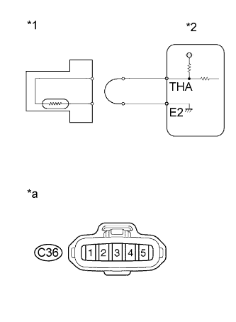
Disconnect the C36 mass air flow meter connector.
Connect terminals 4 and 5 of the mass air flow meter wire harness side connector.
Connect the intelligent tester to the DLC3.
Turn the ignition switch ON and turn the intelligent tester ON.
Enter the following menus: Powertrain / Engine / Data List / Intake Air.
Read the values.
- OK:
- 140°C (284°F) or more
Text in Illustration *1 Mass Air Flow Meter *2 ECM *a Front view of wire harness connector
(to Mass Air Flow Meter)
Reconnect the mass air flow meter connector.
w/o mass air flow meter:
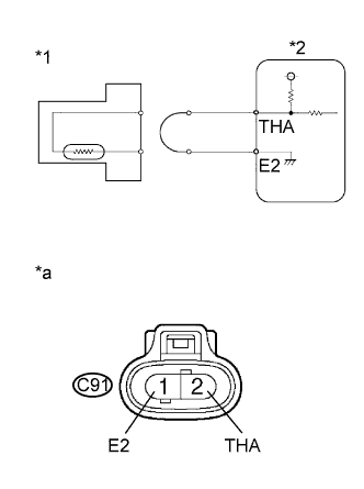
Disconnect the C91 intake air temperature sensor connector.
Connect terminals 1 and 2 of the intake air temperature sensor wire harness side connector.
Connect the intelligent tester to the DLC3.
Turn the ignition switch ON and turn the intelligent tester ON.
Enter the following menus: Powertrain / Engine / Data List / Intake Air.
Read the values.
- OK:
- 140°C (284°F) or more
Text in Illustration *1 Intake Air Temperature Sensor *2 ECM *a Front view of wire harness connector
(to Intake Air Temperature Sensor)
Reconnect the intake air temperature sensor connector.
|
| ||||
|
| ||||
| 3.CHECK HARNESS AND CONNECTOR (INTAKE AIR TEMPERATURE SENSOR - ECM) |
w/ mass air flow meter:
Disconnect the mass air flow meter connector.
Disconnect the ECM connector.
Measure the resistance according to the value(s) in the table below.
- Standard Resistance:
w/ mass air flow meter Tester Connection Condition Specified Condition C36-4 (THA) - C22-31 (THA) Always Below 1 Ω C36-5 (E2) - C22-28 (E2) Always Below 1 Ω
Reconnect the mass air flow meter connector.
Reconnect the ECM connector.
w/o mass air flow meter:
Disconnect the intake air temperature sensor connector.
Disconnect the ECM connector.
Measure the resistance according to the value(s) in the table below.
w/o mass air flow meter Tester Connection Condition Specified Condition C91-2 (THA) - C22-31 (THA) Always Below 1 Ω C91-1 (E2) - C22-28 (E2) Always Below 1 Ω Reconnect the intake air temperature sensor connector.
Reconnect the ECM connector.
|
| ||||
|
| ||||
| 4.READ VALUE USING INTELLIGENT TESTER (CHECK FOR SHORT IN WIRE HARNESS) |
w/ mass air flow meter:
Disconnect the mass air flow meter connector.
Connect the intelligent tester to the DLC3.
Turn the ignition switch to ON and turn the tester on.
Enter the following menus: Powertrain / Engine and ECT / Data List / Intake Air.
Read the value.
- OK:
- -40°C (-40°F)
Text in Illustration *1 Mass Air Flow Meter *2 ECM Reconnect the mass air flow meter connector.
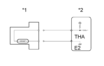 |
w/o mass air flow meter:
Disconnect the intake air temperature sensor connector.
Connect the intelligent tester to the DLC3.
Turn the ignition switch to ON and turn the tester on.
Enter the following menus: Powertrain / Engine and ECT / Data List / Intake Air.
Read the value.
- OK:
- -40°C (-40°F)
Text in Illustration *1 Intake Air Temperature Sensor *2 ECM Reconnect the intake air temperature sensor connector.
|
|
| ||||
|
| ||||
| 5.CHECK HARNESS AND CONNECTOR (INTAKE AIR TEMPERATURE SENSOR - ECM) |
w/ mass air flow meter:
Disconnect the mass air flow meter connector.
Disconnect the ECM connector.
Measure the resistance according to the value(s) in the table below.
- Standard Resistance:
w/ mass air flow meter Tester Connection Condition Specified Condition C36-4 (THA) or C22-31 (THA) - Body ground Always 10 kΩ or higher
Reconnect the mass air flow meter connector.
Reconnect the ECM connector.
w/o mass air flow meter:
Disconnect the intake air temperature sensor connector.
Disconnect the ECM connector.
Measure the resistance according to the value(s) in the table below.
w/o mass air flow meter Tester Connection Condition Specified Condition C91-1 (THA) or C22-31 (THA) - Body ground Always 10 kΩ or higher Reconnect the intake air temperature sensor connector.
Reconnect the ECM connector.
|
| ||||
| OK | |
| 6.REPLACE ECM |
Replace the ECM (HILUX_TGN26 RM0000043H100GX.html).
|
| ||||
| 7.CONFIRM GOOD CONNECTION TO SENSOR. IF OK, REPLACE INTAKE AIR TEMPERATURE SENSOR |
Replace the mass air flow meter (w/ mass air flow meter) (HILUX_TGN26 RM000000VHD041X.html).
Replace the intake air temperature sensor (w/o mass air flow meter) (HILUX_TGN26 RM0000014XP017X.html).
|
| ||||
| 8.REPAIR OR REPLACE HARNESS OR CONNECTOR |
Repair or replace the harness or connector.
|
| ||||
| 9.CONFIRM GOOD CONNECTION TO ECM. IF OK, REPLACE ECM. |
Replace the ECM (HILUX_TGN26 RM0000043H100GX.html).
|
| ||||
| 10.REPLACE INTAKE AIR TEMPERATURE SENSOR |
Replace the mass air flow meter (w/ mass air flow meter) (HILUX_TGN26 RM000000VHD041X.html).
Replace the intake air temperature sensor (w/o mass air flow meter) (HILUX_TGN26 RM0000014XP017X.html).
| NEXT | |
| 11.CONFIRM WHETHER MALFUNCTION HAS BEEN SUCCESSFULLY REPAIRED |
Connect the intelligent tester to the DLC3.
Clear the DTCs (HILUX_TGN26 RM000000PDK0SWX.html).
Turn the ignition switch to ON for 1 second.
Enter the following menus: Powertrain / Engine and ECT / DTC.
Confirm that the DTC is not output again.
| NEXT | ||
| ||