Lexus IS250 IS220d GSE20 ALE20 - SUPPLEMENTAL RESTRAINT SYSTEM
FRONT AIRBAG SENSOR - INSTALLATION
- HINT:
| 1. INSTALL FRONT AIRBAG SENSOR |
Check that the engine switch is off.
Check that the battery negative (-) terminal is disconnected.
- CAUTION:
- After disconnecting the negative battery terminal, wait for at least 90 seconds before starting the operation.

Connect the connector.
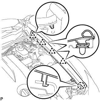
Install the front airbag sensor with the 2 bolts.
- Torque:
- 9.0 N*m{ 92 kgf*cm, 80 in.*lbf}
- NOTICE:
Check that there is no looseness in the installation parts of the front airbag sensor.
| 2. INSTALL HEADLIGHT ASSEMBLY |

Install the headlight assembly with the headlight bracket pin.
Install the 3 bolts.
Connect the connector.
| 3. INSTALL FRONT BUMPER ASSEMBLY |
| 4. INSTALL FRONT UPPER FENDER PROTECTOR LH |
Engage the claw and the 3 clips, then install the front upper fender protector LH.
Engage the clip on the rubber portion of the cowl top ventilator louver sub-assembly to the front fender protector upper LH.
| 5. INSTALL ENGINE ROOM SIDE COVER LH |
| 6. INSTALL COOL AIR INTAKE DUCT SEAL |
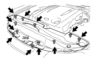
Install the intake duct seal with the 11 clips.
| 7. CONNECT CABLE TO NEGATIVE BATTERY TERMINAL |
| 8. INSPECT SRS WARNING LIGHT |
Inspect the SRS warning light .
| 9. VEHICLE PREPARATION FOR HEADLIGHT AIM ADJUSTMENT |
Prepare the vehicle:
| 10. PREPARATION FOR HEADLIGHT AIMING (Using a tester) |

Prepare the vehicle according to the following conditions:
- NOTICE:
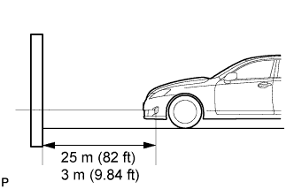
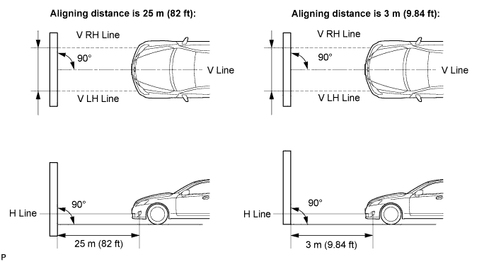
- A distance of 25 m (82 ft) between the vehicle (headlight bulb center) and the wall is necessary for proper aim adjustment. If unavailable, secure a distance of exactly 3 m (9.84 ft) for check and adjustment. (The target zone will change with the distance, so follow the instructions in the illustration.)
Prepare a piece of thick white paper (approximately 2 m (6.6 ft) (height) x 4 m (13.1 ft) (width)) to use as a screen.
Draw a vertical line down the center of screen (V line).
Set the screen as shown in the illustration.

- HINT:
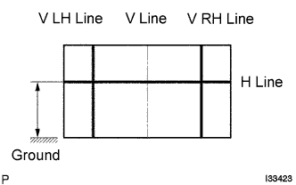
Draw base lines (H line, V LH, V RH lines) on the screen as shown in the illustration.
- HINT:
H Line (Headlight height):
Draw a horizontal line across the screen so that it passes through the center marks. The H line should be at the same height as the headlight bulb center marks of the low-beam headlights.
V LH Line, V RH Line (Center mark position of left-hand (LH) and right-hand (RH) headlights):
Draw two vertical lines so that they intersect the H line at each center mark (aligned with the center of the low-beam headlight bulbs).
| 11. PREPARATION FOR HEADLIGHT AIMING (Using a screen) |
Prepare the vehicle according to the following conditions:
- NOTICE:
- A distance of 25 m (82 ft) between the vehicle (headlight bulb center) and the wall is necessary for proper aim adjustment. If unavailable, secure a distance of exactly 3 m (9.84 ft) for check and adjustment. (The target zone will change with the distance, so follow the instructions in the illustration.)
Prepare a piece of thick white paper (approximately 2 m (6.6 ft) (height) x 4 m (13.1 ft) (width)) to use as a screen.
Draw a vertical line down the center of screen (V line).
Set the screen as shown in the illustration.
- HINT:
Draw base lines (H line, V LH, V RH lines) on the screen as shown in the illustration.
- HINT:
H Line (Headlight height):
Draw a horizontal line across the screen so that it passes through the center marks. The H line should be at the same height as the headlight bulb center marks of the low-beam headlights.
V LH Line, V RH Line (Center mark position of left-hand (LH) and right-hand (RH) headlights):
Draw two vertical lines so that they intersect the H line at each center mark (aligned with the center of the low-beam headlight bulbs).
| 12. INSPECT HEADLIGHT AIMING |
Cover the headlight or disconnect the connector of the headlight on the opposite side to prevent light from the headlight not being inspected from affecting headlight aiming inspection.
- NOTICE:
- Do not keep the headlight covered for more than 3 minutes. The headlight lens is made of synthetic resin, and may easily melt or be damaged due to heat.
- HINT:
- When checking the aim of the high-beam, cover the low-beam or disconnect the connector.
Start the engine.
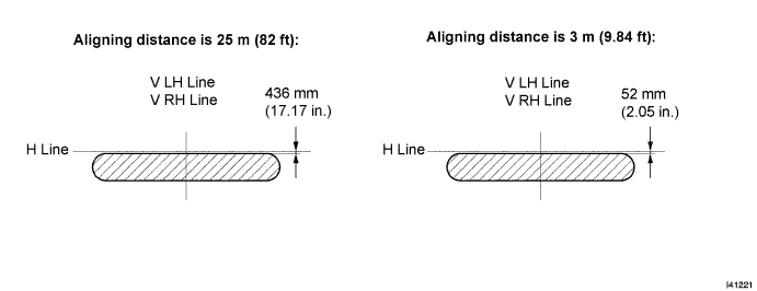
Turn on the headlight and make sure that the cutoff line falls within the specified area, as shown in the illustration.

- HINT:
The cutoff line is 48 mm (1.88 in.) to 698 mm (27.48 in.) below the H line with low-beam (ECE Reg.48).
The cutoff line is 6 mm (0.23 in.) to 84 mm (3.3 in.) below the H line with low-beam (ECE Reg.48).
The cutoff line is 249 mm (9.8 in.) below the H line with low-beam.
The cutoff line is 30 mm (1.18 in.) below the H line with low-beam.
| 13. ADJUST HEADLIGHT AIMING |

Adjust the aim vertically:
Adjust the headlight aim into the specified range by turning aiming screw A with a screwdriver.
- NOTICE:
- The final turn of the aiming screw should be made in the clockwise direction. If the screw is tightened excessively, loosen it and then retighten it, so that the final turn of the screw is in the clockwise direction.
- HINT:

Adjust the aim horizontally:
Adjust the headlight aim into the specified range by turning aiming screw B with a screwdriver.
- NOTICE:
- The final turn of the aiming screw should be made in the clockwise direction. If the screw is tightened excessively, loosen it and then retighten it, so that the final turn of the screw is in the clockwise direction.
- HINT:
- Perform low-beam aim adjustment.
| 14. VEHICLE PREPARATION FOR FOG LIGHT AIM |
Prepare the vehicle:
| 15. PREPARATION FOR FOG LIGHT AIMING |
Prepare the vehicle according to the following conditions:
- NOTICE:
- A distance of 25 m (82 ft) between the vehicle (fog light bulb center) and the wall is necessary for proper aim adjustment. If unavailable, secure a distance of exactly 3 m (9.84 ft) for check and adjustment. (The target zone will change with the distance, so follow the instructions in the illustration.)
Prepare a piece of thick white paper (approximately 2 m (6.6 ft) (height) x 4 m (13.1 ft) (width)) to use as a screen.
Draw a vertical line down the center of screen (V line).
Set the screen as shown in the illustration.
- HINT:
Draw base lines (H line, V LH, V RH lines) on the screen as shown in the illustration.
- HINT:
- Mark the fog light bulb center marks on the screen. If the center mark cannot be observed on the fog light, use the center of the fog light bulb or the manufacturer's name marked on the fog light as the center mark.
H Line (Fog light height):
Draw a horizontal line across the screen so that it passes through the center marks. The H line should be at the same height as the fog light bulb center marks of the low-beam fog lights.
V LH Line, V RH Line (Center mark position of left-hand (LH) and right-hand (RH) fog lights):
Draw two vertical lines so that they intersect the H line at each center mark.
| 16. INSPECT FOG LIGHT AIMING |
Cover the fog light or disconnect the connector of the fog light on the opposite side to prevent light from the fog light not being inspected from affecting fog light aiming inspection.
Start the engine.
Turn on the fog light and make sure that the cutoff line falls within the specified area, as shown in the illustration.
| 17. ADJUST FOG LIGHT AIMING |
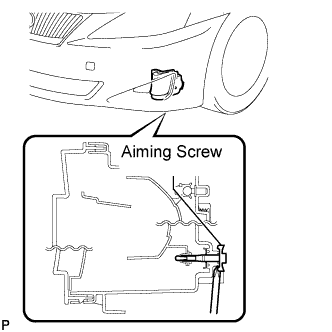
Adjust the fog light aim into the specified range by turning the aiming screw with a screwdriver.
- NOTICE:
- The final turn of the aiming screw should be made in the clockwise direction. If the screw is tightened excessively, loosen it and then retighten it, so that the final turn of the screw is in the clockwise direction.
| 18. PERFORM INITIALIZATION |
Perform initialization .
- HINT:
- Some systems need initialization after reconnecting the cable to the negative battery terminal.