Dtc P245C Egr Cooler Bypass Control Circuit Low
DESCRIPTION
WIRING DIAGRAM
INSPECTION PROCEDURE
INSPECT VACUUM SWITCHING VALVE (FOR EGR BYPASS VALVE)
CHECK VACUUM SWITCHING VALVE (FOR EGR BYPASS VALVE) (POWER SOURCE CIRCUIT)
CHECK HARNESS AND CONNECTOR (VACUUM SWITCHING VALVE (FOR EGR BYPASS VALVE) - ECM)
REPLACE ECM
REPLACE VACUUM SWITCHING VALVE (FOR EGR BYPASS VALVE)
REPAIR OR REPLACE HARNESS OR CONNECTOR
CONFIRM WHETHER MALFUNCTION HAS BEEN SUCCESSFULLY REPAIRED
DTC P245C EGR Cooler Bypass Control Circuit Low |
DTC P245D EGR Cooler Bypass Control Circuit High |
DESCRIPTION
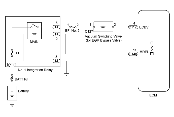
The vacuum switching valve (for EGR bypass valve) is controlled by the ECM, and the opening and closing of the EGR cooler bypass valve is performed according to the vacuum applied by the vacuum pump.P245CDTC Detection Drive Pattern
| DTC Detection Condition
| Trouble Area
|
Ignition switch ON for 3 seconds
| Open or short in the vacuum switching valve (for EGR bypass valve) for 3 seconds (1 trip detection logic).
| - Open or short in vacuum switching valve (for EGR bypass valve) circuit
- Vacuum switching valve (for EGR bypass valve)
- ECM
|
P245DDTC Detection Drive Pattern
| DTC Detection Condition
| Trouble Area
|
Ignition switch ON for 3 seconds
| Open or short in the vacuum switching valve (for EGR bypass valve) for 3 seconds (1 trip detection logic).
| - Open or short in vacuum switching valve (for EGR bypass valve) circuit
- Vacuum switching valve (for EGR bypass valve)
- ECM
|
WIRING DIAGRAM
INSPECTION PROCEDURE
- NOTICE:
- Inspect the fuses of circuits related to this system before performing the following inspection procedure.
- After replacing the ECM, the new ECM needs registration (HILUX_TGN26 RM0000012XK070X.html) and initialization (HILUX_TGN26 RM000000TIN057X.html).
- After replacing the fuel supply pump assembly, the ECM needs initialization (HILUX_TGN26 RM000000TIN057X.html).
- After replacing an injector assembly, the ECM needs registration (HILUX_TGN26 RM0000012XK070X.html).
- HINT:
- Read freeze frame data using the intelligent tester. Freeze frame data records the engine condition when malfunctions are detected. When troubleshooting, freeze frame data can help determine if the vehicle was moving or stationary, if the engine was warmed up or not, and other data from the time the malfunction occurred.
| 1.INSPECT VACUUM SWITCHING VALVE (FOR EGR BYPASS VALVE) |
Inspect the vacuum switching valve (for EGR bypass valve) (HILUX_TGN26 RM00000141C019X_01_0003.html).
| 2.CHECK VACUUM SWITCHING VALVE (FOR EGR BYPASS VALVE) (POWER SOURCE CIRCUIT) |
Disconnect the vacuum switching valve (for EGR bypass valve) connector.
Measure the voltage according to the value(s) in the table below.
- Standard Voltage:
Tester Connection
| Switch Condition
| Specified Condition
|
C127-1 - Body ground
| Ignition switch ON
| 11 to 14 V
|
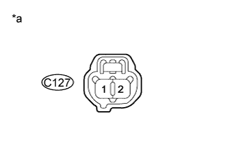
Text in Illustration*a
| Front view of wire harness connector
(to Vacuum Switching Valve (for EGR Bypass Valve))
|
Reconnect the vacuum switching valve (for EGR bypass valve) connector.
| 3.CHECK HARNESS AND CONNECTOR (VACUUM SWITCHING VALVE (FOR EGR BYPASS VALVE) - ECM) |
Disconnect the vacuum switching valve (for EGR bypass valve) connector.
Disconnect the ECM connector.
Measure the resistance according to the value(s) in the table below.
- Standard Resistance:
Tester Connection
| Condition
| Specified Condition
|
C127-2 - C112-4 (ECBV)
| Always
| Below 1 Ω
|
C127-2 or C112-4 (ECBV) - Body ground
| Always
| 10 kΩ or higher
|
Reconnect the vacuum switching valve (for EGR bypass valve) connector.
Reconnect the ECM connector.
Replace the ECM (HILUX_TGN26 RM0000013Z001HX.html).
| 5.REPLACE VACUUM SWITCHING VALVE (FOR EGR BYPASS VALVE) |
Replace the vacuum switching valve (for EGR bypass valve) (HILUX_TGN26 RM000004QWO00GX_02_0010.html).
| 6.REPAIR OR REPLACE HARNESS OR CONNECTOR |
Repair or replace the harness or connector.
- HINT:
- If the voltage at the vacuum switching valve (for EGR bypass valve) connector is not 11 to 14 V, repair or replace the harness and connector between the vacuum switching valve (for EGR bypass valve) and MAIN relay (including the EFI No. 2 fuse).
| 7.CONFIRM WHETHER MALFUNCTION HAS BEEN SUCCESSFULLY REPAIRED |
Connect the intelligent tester to the DLC3.
Clear the DTCs (HILUX_TGN26 RM000000PDK11ZX.html).
Turn the ignition switch to ON for 3 seconds.
Enter the following menus: Powertrain / Engine and ECT / DTC.
Confirm that the DTC is not output again.