Power Window Control System (For Sedan) Driver Side Power Window Does Not Operate With Power Window Master Switch
DESCRIPTION
WIRING DIAGRAM
INSPECTION PROCEDURE
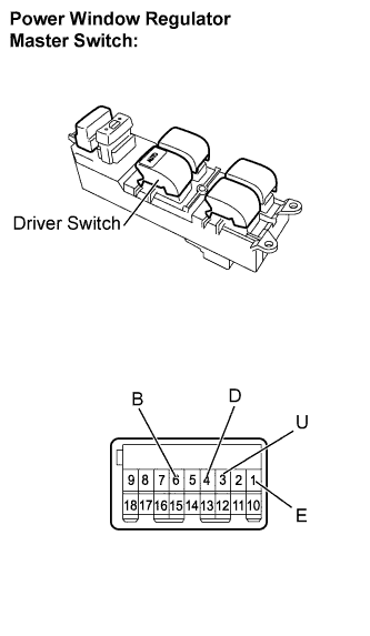
INSPECT POWER WINDOW REGULATOR MASTER SWITCH ASSEMBLY (DRIVER SWITCH)
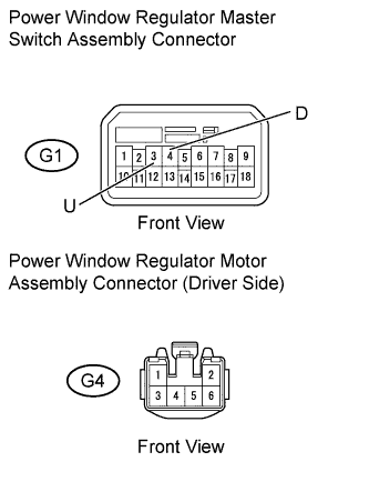
CHECK HARNESS AND CONNECTOR (MASTER SWITCH - MOTOR (DRIVER SIDE))
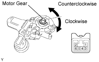
INSPECT POWER WINDOW REGULATOR MOTOR ASSEMBLY (DRIVER SIDE)
POWER WINDOW CONTROL SYSTEM (for Sedan) - Driver Side Power Window does not Operate with Power Window Master Switch |
DESCRIPTION
If the manual UP / DOWN and AUTO DOWN functions do not operate, a malfunction may exist in the power window regulator master switch, power window regulator motor or wire harness.
WIRING DIAGRAM
INSPECTION PROCEDURE
| 1.INSPECT POWER WINDOW REGULATOR MASTER SWITCH ASSEMBLY (DRIVER SWITCH) |
Remove the power window regulator master switch assembly.
Measure the resistance of the switch when the switch is operated.
- Standard resistance:
Window Lock Switch Condition
| Power Window Switch Condition
| Tester Connection
| Specified Condition
|
Always
(ON / OFF)
| UP
| 1 (E) - 4 (D)
3 (U) - 6 (B)
| Below 1 Ω
|
Always
(ON / OFF)
| OFF
| 1 (E) - 3 (U)
1 (E) - 4 (D)
| Below 1 Ω
|
Always
(ON / OFF)
| DOWN
| 1 (E) - 3 (U)
6 (B) - 4 (D)
| Below 1 Ω
|
Always
(ON / OFF)
| AUTO DOWN
| 1 (E) - 3 (U)
6 (B) - 4 (D)
| Below 1 Ω
|
Reinstall the power window regulator master switch assembly.
| 2.CHECK HARNESS AND CONNECTOR (MASTER SWITCH - MOTOR (DRIVER SIDE)) |
Disconnect the G1 power window regulator master switch assembly connector.
Disconnect the G4 power window regulator motor assembly connector.
Measure the resistance of the wire harness side connectors.
- Standard resistance:
Tester Connection
| Specified Condition
|
G1-4 (D) - G4-1
| Below 1 Ω
|
G1-3 (U) - G4-2
| Below 1 Ω
|
G1-4 (D) or G4-1 - Body ground
| 10 kΩ or higher
|
G1-3 (U) or G4-2 - Body ground
| 10 kΩ or higher
|
Reconnect the G1 power window regulator master switch assembly connector.
Reconnect the G4 power window regulator motor assembly connector.
| | REPAIR OR REPLACE HARNESS OR CONNECTOR |
|
|
| 3.INSPECT POWER WINDOW REGULATOR MOTOR ASSEMBLY (DRIVER SIDE) |
Remove the power window regulator motor assembly.
Apply battery voltage to connector terminals 1 and 2.
- NOTICE:
- Do not apply battery voltage to any terminals except terminals 1 and 2.
Check that the motor gear rotates smoothly as follows.
- OK:
Measurement Condition
| Specified Condition
|
Battery positive (+) → 1
Battery negative (-) → 2
| Motor gear rotates counterclockwise
|
Battery positive (+) → 2
Battery negative (-) → 1
| Motor gear rotates clockwise
|
Reinstall the power window regulator motor assembly