Air Conditioning System (For Hatchback) Ptc Heater Circuit
DESCRIPTION
WIRING DIAGRAM
INSPECTION PROCEDURE
PERFORM ACTIVE TEST USING TECHSTREAM
INSPECT QUICK HEATER ASSEMBLY
PERFORM ACTIVE TEST USING TECHSTREAM
CHECK HARNESS AND CONNECTOR (NO. 2 INTEGRATION RELAY - BATTERY AND IG1 NO. 1 RELAY)
CHECK HARNESS AND CONNECTOR (NO. 2 INTEGRATION RELAY - BODY GROUND)
PERFORM ACTIVE TEST USING TECHSTREAM
CHECK HARNESS AND CONNECTOR (NO. 2 INTEGRATION RELAY - AIR CONDITIONING AMPLIFIER ASSEMBLY)
AIR CONDITIONING SYSTEM (for Hatchback) - PTC Heater Circuit |
DESCRIPTION
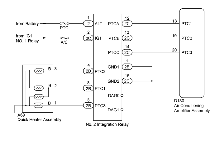
The No. 2 integration relay is controlled in accordance with signals from the air conditioning amplifier assembly and power is supplied to the quick heater assembly installed on the radiator heater unit.
WIRING DIAGRAM
INSPECTION PROCEDURE
- NOTICE:
- Inspect the fuses for circuits related to this system before performing the following inspection procedures.
| 1.PERFORM ACTIVE TEST USING TECHSTREAM |
Connect the Techstream to the DLC3.
Turn the ignition switch to ON.
Turn the Techstream on.
Enter the following menus: Body Electrical / Air Conditioner / Active Test.
According to the display on the Techstream, perform the Active Test.
Air ConditionerTester Display
| Test Part
| Control Range
| Diagnostic Note
|
Heater Active Level
| Heater level
| Min.: 0, Max.: 3
| -
|
Measure the voltage according to the value(s) in the table below while performing the Active Test.
- Standard Voltage:
Tester Connection
| Condition
| Specified Condition
|
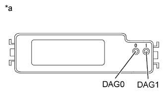
0 (DAG0) - Body ground
| Heater Active Level 1 to 3
| 3.5 to 5 V
|
1 (DAG1) - Body ground
| Heater Active Level 1 to 3
| 3.5 to 5 V
|
Text in Illustration*a
| Upper View of No. 2 Integration Relay
|
| 2.INSPECT QUICK HEATER ASSEMBLY |
Inspect the quick heater assembly (YARIS_NCP93 RM00000315V01EX.html).
| 3.PERFORM ACTIVE TEST USING TECHSTREAM |
Disconnect the A69 quick heater assembly connector.
Connect the Techstream to the DLC3.
Start the engine.
Turn the Techstream on.
Enter the following menus: Body Electrical / Air Conditioner / Active Test.
According to the display on the Techstream, perform the Active Test.
Air ConditionerTester Display
| Test Part
| Control Range
| Diagnostic Note
|
Heater Active Level
| Heater level
| Min.: 0, Max.: 3
| -
|
Measure the voltage according to the value(s) in the table below while performing the Active Test.
- Standard Voltage:
Tester Connection
| Condition
| Specified Condition
|
A69-1 (B) - Body ground
| Heater Active Level 0
| Below 1 V
|
Heater Active Level 1
| Below 1 V
|
Heater Active Level 2
| Below 1 V
|
Heater Active Level 3
| 11 to 14 V
|
A69-2 (B) - Body ground
| Heater Active Level 0
| Below 1 V
|
Heater Active Level 1
| 11 to 14 V
|
Heater Active Level 2
| 11 to 14 V
|
Heater Active Level 3
| 11 to 14 V
|
A69-3 (B) - Body ground
| Heater Active Level 0
| Below 1 V
|
Heater Active Level 1
| Below 1 V
|
Heater Active Level 2
| 11 to 14 V
|
Heater Active Level 3
| 11 to 14 V
|
Text in Illustration*a
| Front view of wire harness connector
(to Quick Heater Assembly)
|
| | REPAIR OR REPLACE HARNESS OR CONNECTOR (QUICK HEATER ASSEMBLY - NO. 2 INTEGRATION RELAY) |
|
|
| 4.CHECK HARNESS AND CONNECTOR (NO. 2 INTEGRATION RELAY - BATTERY AND IG1 NO. 1 RELAY) |
Remove the No. 2 integration relay from the No. 2 engine room relay block.
Measure the voltage according to the value(s) in the table below.
- Standard Voltage:
Tester Connection
| Switch Condition
| Specified Condition
|
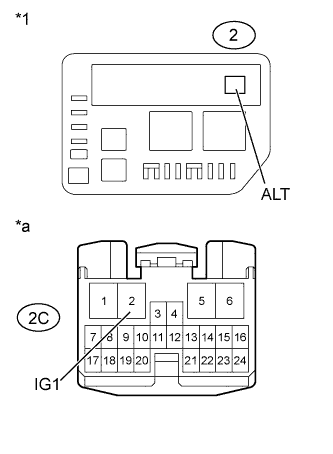
2-1 (ALT) - Body ground
| Always
| 11 to 14 V
|
2C-2 (IG1) - Body ground
| Ignition switch ON
| 11 to 14 V
|
Text in Illustration*1
| No. 2 Engine Room Relay Block
|
*a
| Front view of wire harness connector
(to No. 2 Integration Relay)
|
| | REPAIR OR REPLACE HARNESS OR CONNECTOR |
|
|
| 5.CHECK HARNESS AND CONNECTOR (NO. 2 INTEGRATION RELAY - BODY GROUND) |
Remove the No. 2 integration relay from the No. 2 engine room relay block.
Measure the resistance according to the value(s) in the table below.
- Standard Resistance:
Tester Connection
| Condition
| Specified Condition
|
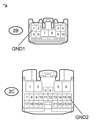
2B-1 (GND1) - Body ground
| Always
| Below 1 Ω
|
2C-16 (GND2) - Body ground
| Always
| Below 1 Ω
|
Text in Illustration*a
| Front view of wire harness connector
(to No. 2 Integration Relay)
|
| | REPAIR OR REPLACE HARNESS OR CONNECTOR |
|
|
| 6.PERFORM ACTIVE TEST USING TECHSTREAM |
Remove the No. 2 integration relay from the No. 2 engine room relay block.
Connect the Techstream to the DLC3.
Start the engine.
Turn the Techstream on.
Enter the following menus: Body Electrical / Air Conditioner / Active Test.
According to the display on the Techstream, perform the Active Test.
Air ConditionerTester Display
| Test Part
| Control Range
| Diagnostic Note
|
Heater Active Level
| Heater level
| Min.: 0, Max.: 3
| -
|
Measure the voltage according to the value(s) in the table below while performing the Active Test.
- Standard Voltage:
Tester Connection
| Condition
| Specified Condition
|
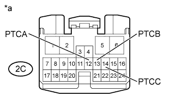
2C-12 (PTCA) - Body ground
| Heater Active Level 0
| Below 1 V
|
Heater Active Level 1
| 11 to 14 V
|
Heater Active Level 2
| 11 to 14 V
|
Heater Active Level 3
| 11 to 14 V
|
2C-13 (PTCB) - Body ground
| Heater Active Level 0
| Below 1 V
|
Heater Active Level 1
| Below 1 V
|
Heater Active Level 2
| 11 to 14 V
|
Heater Active Level 3
| 11 to 14 V
|
2C-14 (PTCC) - Body ground
| Heater Active Level 0
| Below 1 V
|
Heater Active Level 1
| Below 1 V
|
Heater Active Level 2
| Below 1 V
|
Heater Active Level 3
| 11 to 14 V
|
Text in Illustration*a
| Front view of wire harness connector
(to No. 2 Integration Relay)
|
| OK |
|
|
|
| REPLACE NO. 2 INTEGRATION RELAY |
|
| 7.CHECK HARNESS AND CONNECTOR (NO. 2 INTEGRATION RELAY - AIR CONDITIONING AMPLIFIER ASSEMBLY) |
Remove the No. 2 integration relay from the No. 2 engine room relay block.
Disconnect the D130 air conditioning amplifier assembly connector.
Measure the resistance according to the value(s) in the table below.
- Standard Resistance:
Tester Connection
| Condition
| Specified Condition
|
2C-12 (PTCA) - D130-13 (PTC1)
| Always
| Below 1 Ω
|
2C-13 (PTCB) - D130-19 (PTC2)
| Always
| Below 1 Ω
|
2C-14 (PTCC) - D130-20 (PTC3)
| Always
| Below 1 Ω
|
2C-12 (PTCA) - Body ground
| Always
| 10 kΩ or higher
|
2C-13 (PTCB) - Body ground
| Always
| 10 kΩ or higher
|
2C-14 (PTCC) - Body ground
| Always
| 10 kΩ or higher
|
| | REPAIR OR REPLACE HARNESS OR CONNECTOR |
|
|