Dtc B1610/13 Front Airbag Sensor Rh Circuit Malfunction
DESCRIPTION
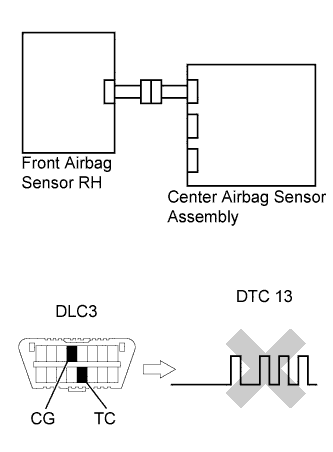
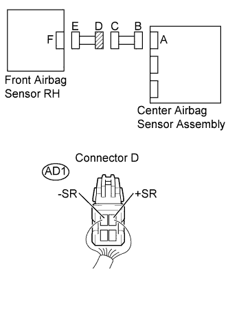
WIRING DIAGRAM
INSPECTION PROCEDURE
CHECK DTC
CHECK CONNECTION OF CONNECTORS
CHECK FRONT AIRBAG SENSOR RH CIRCUIT (FOR OPEN)
CHECK FRONT AIRBAG SENSOR RH CIRCUIT (FOR SHORT)
CHECK FRONT AIRBAG SENSOR RH CIRCUIT (TO B+)
CHECK FRONT AIRBAG SENSOR RH CIRCUIT (TO GROUND)
CHECK FRONT AIRBAG SENSOR RH
CHECK ENGINE ROOM MAIN WIRE (FOR OPEN)
CHECK ENGINE ROOM MAIN WIRE (FOR SHORT)
CHECK ENGINE ROOM MAIN WIRE (TO B+)
CHECK ENGINE ROOM MAIN WIRE (TO GROUND)
DTC B1610/13 Front Airbag Sensor RH Circuit Malfunction |
DESCRIPTION
The front airbag sensor RH consists of part including the diagnostic circuit and the frontal deceleration sensor.When the center airbag sensor assembly receives signals from the frontal deceleration sensor, it determines whether or not the SRS should be activated.DTC B1610/13 is set when a malfunction is detected in the front airbag sensor RH circuit.DTC No.
| DTC Detecting Condition
| Trouble Area
|
B1610/13
| - Center airbag sensor assembly detects line short circuit signal, open circuit signal, short circuit to ground signal or short circuit to B+ signal in front airbag sensor RH circuit for 2 seconds.
- Front airbag sensor RH malfunction
- Center airbag sensor assembly malfunction
| - Instrument panel wire
- Engine room main wire
- Front airbag sensor RH
- Center airbag sensor assembly
|
WIRING DIAGRAM
INSPECTION PROCEDURE
- NOTICE:
- In order to prevent unexpected airbag deployment, disconnect the following connectors before inspecting parts such as wire harnesses, if the application of tester probes to the center airbag sensor assembly connector is necessary.
- Turn the ignition switch to the lock position.
- Disconnect the negative (-) terminal cable from the battery, and wait for at least 90 seconds.
- Disconnect the connector from the center airbag sensor assembly.
- Disconnect the connectors from the steering pad.
- Disconnect the connectors from the front passenger airbag assembly.
- Disconnect the connector from the front seat outer belt assembly LH.
- Disconnect the connector from the front seat outer belt assembly RH.
- HINT:
- Skip the following steps if side and curtain shield airbags are not fitted.
- Disconnect the connector from the front seat side airbag assembly LH.
- Disconnect the connector from the front seat side airbag assembly RH.
- Disconnect the connector from the curtain shield airbag assembly LH.
- Disconnect the connector from the curtain shield airbag assembly RH.
Turn the ignition switch on, and wait for at least 60 seconds.
Clear the DTCs stored in the memory (YARIS_NCP93 RM000000XFE0D2X.html).
Turn the ignition switch off.
Turn the ignition switch on, and wait for at least 60 seconds.
Check the DTCs (YARIS_NCP93 RM000000XFE0D2X.html).
- OK:
- DTC B1610/13 is not output.
- HINT:
- DTCs other than DTC B1610/13 may be output at this time, but they are not related to this check.
| | USE SIMULATION METHOD TO CHECK |
|
|
| 2.CHECK CONNECTION OF CONNECTORS |
Turn the ignition switch off.
Disconnect the negative (-) terminal cable from the battery, and wait for at least 90 seconds.
Check that the connectors are properly connected to the center airbag sensor assembly and the front airbag sensor RH.
- OK:
- The connectors are properly connected.
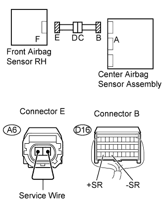
| 3.CHECK FRONT AIRBAG SENSOR RH CIRCUIT (FOR OPEN) |
Disconnect the connectors from the center airbag sensor assembly and the front airbag sensor RH.
Using a service wire, connect A6-1 and A6-2 of connector E.
- NOTICE:
- Do not forcibly insert the service wire into the terminals of the connector when connecting.
Measure the resistance.
- Standard resistance:
Tester Connection
| Condition
| Specified Condition
|
D16-29 (+SR) - D16-27 (-SR)
| Always
| Below 1 Ω
|
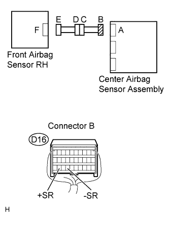
| 4.CHECK FRONT AIRBAG SENSOR RH CIRCUIT (FOR SHORT) |
Disconnect the service wire from connector E.
Measure the resistance.
- Standard resistance:
Tester Connection
| Condition
| Specified Condition
|
D16-29 (+SR) - D16-27 (-SR)
| Always
| 1 MΩ or higher
|
| 5.CHECK FRONT AIRBAG SENSOR RH CIRCUIT (TO B+) |
Connect the negative (-) terminal cable to the battery, and wait for at least 2 seconds.
Turn the ignition switch on.
Measure the voltage.
- Standard voltage:
Tester Connection
| Switch Condition
| Specified Condition
|
D16-29 (+SR) - Body ground
| Ignition switch on
| Below 1 V
|
D16-27 (-SR) - Body ground
| Ignition switch on
| Below 1 V
|
| 6.CHECK FRONT AIRBAG SENSOR RH CIRCUIT (TO GROUND) |
Turn the ignition switch off.
Disconnect the negative (-) terminal cable from the battery, and wait for at least 90 seconds.
Measure the resistance.
- Standard resistance:
Tester Connection
| Condition
| Specified Condition
|
D16-29 (+SR) - Body ground
| Always
| 1 MΩ or higher
|
D16-27 (-SR) - Body ground
| Always
| 1 MΩ or higher
|
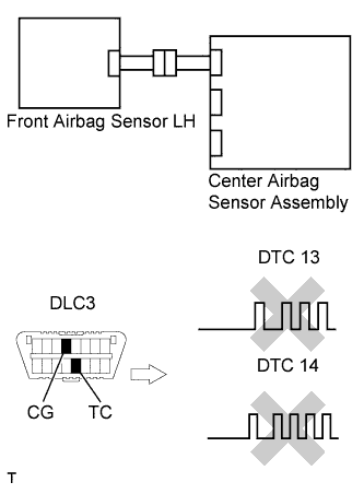
| 7.CHECK FRONT AIRBAG SENSOR RH |
Connect the connectors to the center airbag sensor assembly.
Interchange the front airbag sensor LH with RH and connect the connectors to them.
Connect the negative (-) terminal cable to the battery, and wait for at least 2 seconds.
Turn the ignition switch on, and wait for at least 60 seconds.
Clear the DTCs stored in the memory (YARIS_NCP93 RM000000XFE0D2X.html).
Turn the ignition switch off.
Turn the ignition switch on, and wait for at least 60 seconds.
Check the DTCs (YARIS_NCP93 RM000000XFE0D2X.html).
- Result:
Result
| Proceed to
|
DTC B1610/13 is output.
| A
|
DTC B1615/14 is output.
| B
|
DTC B1610/13 and B1615/14 are not output.
| C
|
- HINT:
- DTCs other than DTC B1610/13 and B1615/14 may be output at this time, but they are not related to this check.
| | REPLACE CENTER AIRBAG SENSOR ASSEMBLY |
|
|
| | REPLACE FRONT AIRBAG SENSOR RH |
|
|
| C |
|
|
|
| USE SIMULATION METHOD TO CHECK |
|
| 8.CHECK ENGINE ROOM MAIN WIRE (FOR OPEN) |
Disconnect the engine room main wire connector from the instrument panel wire.
- HINT:
- The service wire has already been inserted into connector E.
Measure the resistance.
- Standard resistance:
Tester Connection
| Condition
| Specified Condition
|
AD1-1 (+SR) - AD1-2 (-SR)
| Always
| Below 1 Ω
|
| | REPAIR OR REPLACE ENGINE ROOM MAIN WIRE |
|
|
| OK |
|
|
|
| REPAIR OR REPLACE INSTRUMENT PANEL WIRE |
|
| 9.CHECK ENGINE ROOM MAIN WIRE (FOR SHORT) |
Disconnect the service wire from connector E.
Measure the resistance.
- Standard resistance:
Tester Connection
| Condition
| Specified Condition
|
AD1-1 (+SR) - AD1-2 (-SR)
| Always
| 1 MΩ or higher
|
| | REPAIR OR REPLACE ENGINE ROOM MAIN WIRE |
|
|
| OK |
|
|
|
| REPAIR OR REPLACE INSTRUMENT PANEL WIRE |
|
| 10.CHECK ENGINE ROOM MAIN WIRE (TO B+) |
Turn the ignition switch to the lock position.
Disconnect the negative (-) terminal cable from the battery, and wait for at least 90 seconds.
Disconnect the engine room main wire connector from the instrument panel wire.
Connect the negative (-) terminal cable to the battery, and wait for at least 2 seconds.
Turn the ignition switch on.
Measure the voltage.
- Standard voltage:
Tester Connection
| Switch Condition
| Specified Condition
|
AD1-1 (+SR) - Body ground
| Ignition switch on
| Below 1 V
|
AD1-2 (-SR) - Body ground
| Ignition switch on
| Below 1 V
|
| | REPAIR OR REPLACE ENGINE ROOM MAIN WIRE |
|
|
| OK |
|
|
|
| REPAIR OR REPLACE INSTRUMENT PANEL WIRE |
|
| 11.CHECK ENGINE ROOM MAIN WIRE (TO GROUND) |
Disconnect the engine room main wire connector from the instrument panel wire.
Measure the resistance.
- Standard resistance:
Tester Connection
| Condition
| Specified Condition
|
AD1-1 (+SR) - Body ground
| Always
| 1 MΩ or higher
|
AD1-2 (-SR) - Body ground
| Always
| 1 MΩ or higher
|
| | REPAIR OR REPLACE ENGINE ROOM MAIN WIRE |
|
|
| OK |
|
|
|
| REPAIR OR REPLACE INSTRUMENT PANEL WIRE |
|