DESCRIPTION
WIRING DIAGRAM
INSPECTION PROCEDURE
CHECK BUZZER (SEAT BELT, KEY REMINDER, TAILLIGHT REMINDER)
CHECK SUPPLEMENTAL RESTRAINT SYSTEM
CHECK OCCUPANT CLASSIFICATION SYSTEM
CHECK KEY REMINDER FUNCTION
READ VALUE USING TECHSTREAM (FRONT DOOR COURTESY SWITCH (DRIVER SIDE))
READ VALUE USING TECHSTREAM (UNLOCK WARNING SWITCH)
INSPECT UNLOCK WARNING SWITCH ASSEMBLY
CHECK HARNESS AND CONNECTOR (UNLOCK WARNING SWITCH ASSEMBLY - MAIN BODY ECU)
INSPECT FRONT DOOR COURTESY SWITCH (DRIVER SIDE)
CHECK HARNESS AND CONNECTOR (FRONT DOOR COURTESY SWITCH - MAIN BODY ECU)
READ VALUE USING TECHSTREAM (FRONT DOOR COURTESY SWITCH)
INSPECT FRONT DOOR COURTESY SWITCH (DRIVER SIDE)
CHECK HARNESS AND CONNECTOR (FRONT DOOR COURTESY SWITCH - MAIN BODY ECU)
METER / GAUGE SYSTEM (for Sedan) - Warning Buzzer does not Sound |
DESCRIPTION
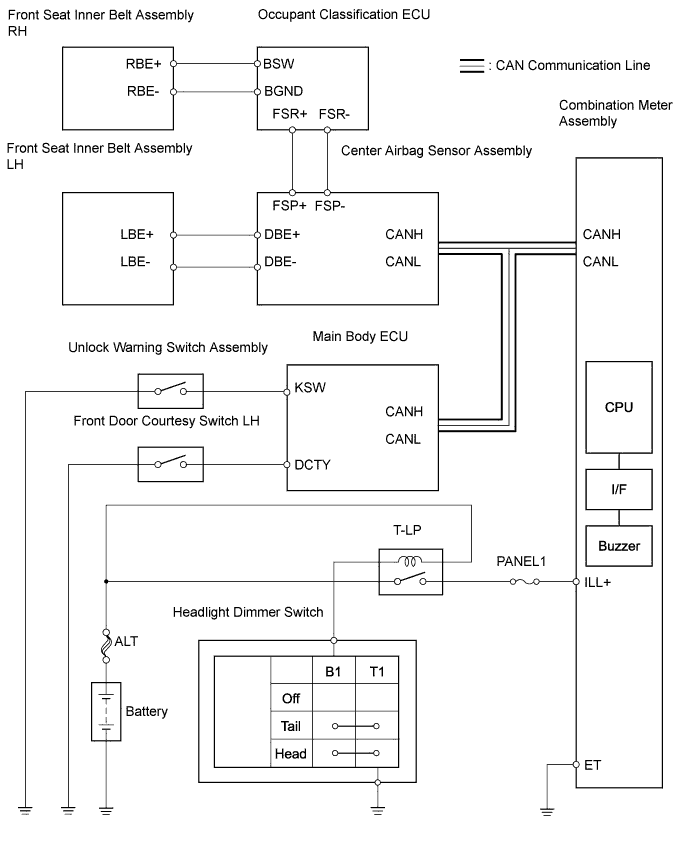
The combination meter assembly controls the buzzers in accordance with signals from the center airbag sensor assembly, the main body ECU and the taillight relay.- HINT:
- The main body ECU receives signals from the center airbag sensor assembly and transmits them to the combination meter assembly.
WIRING DIAGRAM
INSPECTION PROCEDURE
| 1.CHECK BUZZER (SEAT BELT, KEY REMINDER, TAILLIGHT REMINDER) |
Check that the seat belt, key reminder and taillight reminder warning buzzers sound.
- Result:
Result
| Proceed to
|
Seat belt warning buzzer does not sound
(where equipped with seat belt warning system)
| A
|
Key reminder warning buzzer does not sound
(where equipped with key reminder warning system)
| B
|
Taillight reminder warning buzzer does not sound
(Meter illuminations normal)
| C
|
No warning buzzers sound
| D
|
- HINT:
- Seat belt warning buzzer on: Ignition switch is ON, driver or front passenger seat belt is unfastened, and vehicle speed is 12.4mph (20 km/h) or more.
- Key reminder warning buzzer on: Ignition switch is OFF, key is in ignition key cylinder, and driver side door is open.
- Taillight reminder warning buzzer on: Ignition switch is OFF, taillight relay switch is ON, and driver side door is open.
| 2.CHECK SUPPLEMENTAL RESTRAINT SYSTEM |
Connect the Techstream to the DLC3.
Turn the ignition switch ON and turn the tester ON.
Enter the following menus: Body Electrical / SRS Airbag / Trouble Codes.
- Result:
Result
| Proceed to
|
No SRS DTCs are output
| A
|
SRS DTCs are output
| B
|
| 3.CHECK OCCUPANT CLASSIFICATION SYSTEM |
Connect the Techstream to the DLC3.
Turn the ignition switch ON and turn the tester ON.
Enter the following menus: Body Electrical / Occupant Detection / Trouble Codes.
- Result:
Result
| Proceed to
|
No occupant classification system DTCs are output
| A
|
Occupant classification system DTCs are output
| B
|
| 4.CHECK KEY REMINDER FUNCTION |
Ignition switch is OFF.
Key is in ignition key cylinder.
Driver side door is open.
- OK:
- Key reminder warning buzzer ON.
| 5.READ VALUE USING TECHSTREAM (FRONT DOOR COURTESY SWITCH (DRIVER SIDE)) |
Connect the Techstream to the DLC3.
Turn the ignition switch ON and turn the tester ON.
Select the item below from the Data List, and read the value displayed on the Techstream.
- Body Electrical / Main Body / Data List::
Tester Display
| Measurement Item/Range
| Normal Condition
| Diagnostic Note
|
D Door Courtesy SW
| Driver side door courtesy switch signal / ON or OFF
| ON: Driver door is open
OFF: Driver door is closed
| -
|
| 6.READ VALUE USING TECHSTREAM (UNLOCK WARNING SWITCH) |
Connect the Techstream to the DLC3.
Turn the ignition switch ON and turn the tester ON.
Select the item below from the Data List, and read the value displayed on the Techstream.
- Body Electrical / Main Body / Data List::
Tester Display
| Measurement Item/Range
| Normal Condition
| Diagnostic Note
|
Key Unlock Warning SW
| Unlock warning switch signal / ON or OFF
| ON: Key is in ignition key cylinder
OFF: No key is in ignition key cylinder
| -
|
| 7.INSPECT UNLOCK WARNING SWITCH ASSEMBLY |
Disconnect the D19 unlock warning switch assembly connector.
Remove the unlock warning switch assembly.
Measure the resistance.
- Standard resistance:
Tester
Connection
| Condition
| Specified
Condition
|
1 - 2
| Not pushed
| 10 k Ω or higher
|
1 - 2
| Pushed
| Below 1 Ω
|
Reconnect the unlock warning switch assembly.
| | REPLACE UNLOCK WARNING SWITCH ASSEMBLY |
|
|
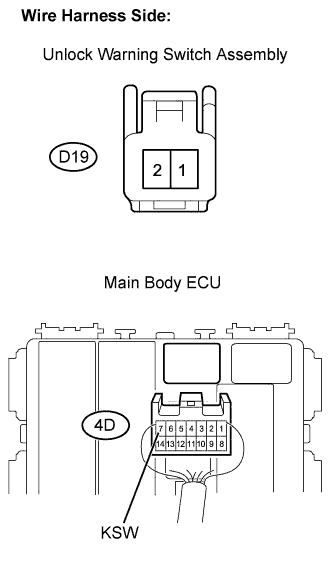
| 8.CHECK HARNESS AND CONNECTOR (UNLOCK WARNING SWITCH ASSEMBLY - MAIN BODY ECU) |
Disconnect the D19 unlock warning switch connector.
Disconnect the 4D main body ECU connector.
Measure the resistance.
- Standard resistance:
Tester Connection
| Specified Condition
|
D19-1 - 4D-7 (KSW)
| Below 1 Ω
|
D19-2 - Body ground
| Below 1 Ω
|
Reconnect the unlock warning switch connector.
Reconnect the main body ECU connector.
| | REPAIR OR REPLACE HARNESS OR CONNECTOR |
|
|
| 9.INSPECT FRONT DOOR COURTESY SWITCH (DRIVER SIDE) |
Disconnect the J2 front door courtesy switch connector.
Measure the resistance.
- Standard resistance:
Tester
Connection
| Condition
| Specified
Condition
|
J2-1 - Body ground
| Not pushed (ON)
| Below 1 Ω
|
J2-1 - Body ground
| Pushed (OFF)
| 10 kΩ or higher
|
Reconnect the front door courtesy switch connector.
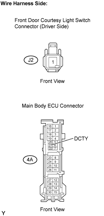
| 10.CHECK HARNESS AND CONNECTOR (FRONT DOOR COURTESY SWITCH - MAIN BODY ECU) |
Disconnect the J2 front door courtesy switch connector.
Disconnect the 4A main body ECU connector.
Measure the resistance.
- Standard resistance:
Tester Connection
| Specified Condition
|
J2-1 - 4A-21 (DCTY)
| Below 1 Ω
|
Reconnect the front door courtesy switch connector.
Reconnect the main body ECU connector.
| | REPAIR OR REPLACE HARNESS OR CONNECTOR |
|
|
| 11.READ VALUE USING TECHSTREAM (FRONT DOOR COURTESY SWITCH) |
Connect the Techstream to the DLC3.
Turn the ignition switch ON and turn the tester ON.
Select the item below from the Data List, and read the value displayed on the Techstream.
- Body Electrical / Main Body / Data List::
Item
| Measurement Item /
Display (Range)
| Normal Condition
| Diagnostic Note
|
D Door Courtesy SW
| Driver door courtesy switch signal /
ON or OFF
| ON: Driver door is open
OFF: Driver door is closed
| -
|
| 12.INSPECT FRONT DOOR COURTESY SWITCH (DRIVER SIDE) |
Disconnect the J2 front door courtesy switch assembly connector.
Measure the resistance.
- Standard resistance:
Tester
Connection
| Condition
| Specified
Condition
|
J2-1 - Body ground
| Not pushed (ON)
| Below 1 Ω
|
J2-1 - Body ground
| Pushed (OFF)
| 10kΩ or higher
|
Reconnect the front door courtesy switch connector.
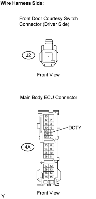
| 13.CHECK HARNESS AND CONNECTOR (FRONT DOOR COURTESY SWITCH - MAIN BODY ECU) |
Disconnect the J2 front door courtesy switch connector.
Disconnect the 4A main body ECU connector.
Measure the resistance.
- Standard resistance:
Tester Connection
| Specified Condition
|
J2-1 - 4A-21 (DCTY)
| Below 1 Ω
|
Reconnect the front door courtesy switch connector.
Reconnect the main body ECU connector.