Vehicle Interior. Yaris. Ncp93, 131
Meter Gauge Display. Yaris. Ncp93, 131
Meter / Gauge System (For Sedan) -- Terminals Of Ecu |
| COMBINATION METER ASSEMBLY |

Disconnect the D1 combination meter assembly connector.
Measure the voltage and resistance of the wire harness side connector.
If the result is not as specified, there may be a malfunction in the wire harness.Terminal No. (Symbol) Wiring Color Terminal Description Condition Specified Condition D1-1 (IG2) - Body ground B - Body ground Ignition switch signal Ignition switch OFF → ON Below 1 V → 11 to 14 V D1-2 (ECU-B) - Body ground L - Body ground Battery Always 11 to 14 V D1-24 (ET) - Body ground BR - Body ground Ground Always Below 1 Ω Disconnect the D76 combination meter assembly connector.
Measure the voltage of the wire harness side connector.
Terminal No. (Symbol) Wiring Color Terminal Description Condition Specified Condition D1-3 (FUEL) - Body ground V - Body ground Fuel level signal Ignition switch ON 11 to 14 V D1-6 (TIRE)*1 - Body ground BE - Body ground Tire pressure warning signal Ignition switch ON,
Tire pressure warning light ON0.9 to 3.2 V Ignition switch ON,
Tire pressure warning light OFF3.2 V or higher D1-7 (ILL-) - Body ground GR - Body ground Light control rheostat signal Ignition switch OFF → ON Pulse generation
(See waveform 1)D1-14 (ILL+) - Body ground G - Body ground Illumination signal Light control switch OFF → ON Below 1 V → 11 to 14 V D1-15 (TC) - Body ground Y - Body ground Tail cancel switch signal Tail cancel switch OFF → ON Below 1 V → 11 to 14 V D1-16 (+S) - Body ground SB - Body ground Vehicle speed signal (Output) Driving at approx. 20 km/h (12 mph) Pulse generation
(See waveform 2)D1-17 (SI) - Body ground P - Body ground Vehicle Speed signal (Input) Driving at approx. 20 km/h (12 mph) Pulse generation
(See waveform 2)D1-20 (CANH) - Body ground G - Body ground CAN communication line Ignition switch ON Pulse generation D1-21 (CANL) - Body ground W - Body ground CAN communication line Ignition switch ON Pulse generation D76-1 (CHG) - Body ground SB*2 - Body ground Charge warning light signal Ignition switch ON
Engine start
Charge warning light
OFF → ON11 to 14 V → Below 1 V L*3 - Body ground D76-2 (SW) - Body ground V - Body ground Brake fluid level warning light signal Ignition switch ON
Brake fluid level warning light
ON → OFFBelow 1 V → 11 to 14 V D76-4 (EFI) - Body ground B - Body ground MIL signal Ignition switch ON
MIL ON → OFFBelow 1 V → 11 to 14 V D76-7 (FOG)*4 - Body ground R - Body ground Front fog signal Ignition switch ON
Front fog light switch
OFF → ONBelow 1 V → 11 to 14 V D76-8 (TURN L) - Body ground LG - Body ground Turn signal LH signal Ignition switch ON
Turn signal LH indicator light
OFF → ON → OFFBelow 1 V → 11 to 14 V → Below 1 V D76-9 (PBLT) - Body ground BE - Body ground Seat belt warning light signal (Passenger side) Ignition switch ON
Front passenger seat belt warning light OFF → ON → OFFBelow 1 V → 11 to 14 V → Below 1 V D76-10 (WLVL)*5 - Body ground W - Body ground Washer level warning signal Ignition switch ON
Washer level warning light ON → OFFBelow 1 V → 11 to 14 V D76-11 (BEAM-) - Body ground P - Body ground HI-BEAM indicator signal (-) Headlight dimmer switch (Hi-BEAM) Hi → Lo Below 1 V → 11 to 14 V D76-12 (S) - Body ground Y - Body ground Oil pressure signal OIL / P warning light ON → OFF Below 1 V → 11 to 14 V D76-13 (HEAD)*6 - Body ground L - Body ground HEAD light indicator signal Light control switch OFF → ON Below 1 V → 11 to 14 V D76-14 (BEAM+) - Body ground GR - Body ground HI-BEAM indicator signal (+) BEAM indicator light OFF → ON Below 1 V → 11 to 14 V D76-15 (TURN R) - Body ground BR - Body ground Turn signal RH signal Turn signal RH indicator light OFF → ON → OFF Below 1 V → 11 to 14 V → Below 1 V D76-16 (IND)*7 - Body ground G - Body ground Taillight indicator signal Light control switch OFF → ON Below 1 V → 11 to 14 V D76-17 (ODO) - Body ground L - Body ground ODO/TRIP switch signal Ignition switch ON 5 V D76-18 (CLK) - Body ground R - Body ground Clock switch signal Ignition switch ACC 5 V D76-19 (E1) - Body ground GR - Body ground Ground Ignition switch ON Below 1 V - *1: w/ Tire Pressure Warning System
- *2: w/ Daytime Running Light
- *3: w/o Daytime Running Light
- *4: w/ Front Fog Light
- *5: w/ Washer Level Warning
- *6: for U.S.A.
- *7: for Canada
Waveform 1: Using an oscilloscope
Terminal Connections D1-7 (ILL-) - Body Ground Tool Setting 5 V/DIV, 50 ms/DIV Condition Ignition switch ON Waveform 2: Using an oscilloscope
Terminal Connections D1-16 (+S) - Body Ground
D1-17 (SI) - Body GroundTool Setting 5 V/DIV, 20 ms/DIV Condition Driving at approximately 12 mph (20 km/h) - HINT:
- As the vehicle speed increases, the cycle of the signal waveform narrows.


- *1: w/ Tire Pressure Warning System
| MAIN BODY ECU |

| *1 | Rear view of Main Body ECU | - | - |

| *1 | Front view of Main Body ECU | - | - |
Disconnect the 4A, 4D and 4E main body ECU connectors.
Measure the resistance of the wire harness side connectors.
If the result is not as specified, there may be a malfunction in the wire harness.Terminal No. (Symbol) Wiring Color Terminal Description Condition Specified Condition 4A-5 (RRCY) - Body ground G - Body ground Rear door courtesy switch signal (LH and RH) Rear door (LH and RH) CLOSED → OPEN 10 kΩ or higher → Below 1 Ω 4A-7 (LGCY) - Body ground SB - Body ground Luggage door courtesy switch signal Luggage door CLOSED → OPEN 10 kΩ or higher → Below 1 Ω 4A-21 (DCTY) - Body ground R - Body ground Front door courtesy switch signal (Driver Side) Front door (Driver Side) CLOSED → OPEN 10 kΩ or higher → Below 1 Ω 4A-24 (PCTY) - Body ground L - Body ground Front door courtesy switch signal (Passenger Side) Front door (Passenger Side) CLOSED → OPEN 10 kΩ or higher → Below 1 Ω 4D-7 (KSW) - Body ground Y - Body ground Key unlock warning switch signal Key inserted → removed 10 kΩ or higher → Below 1 Ω 4E-17 (GND1) - Body ground W-B - Body ground Ground Always Below 1 Ω Reconnect the main body ECU connectors.
Measure the voltage of the wire harness side connectors.
If the result is not as specified, there may be a malfunction in the wire harness.Terminal No. (Symbol) Wiring Color Terminal Description Condition Specified Condition 4C-2 (PKB) - Body ground Y - Body ground Parking brake signal Parking brake warning light ON → OFF Below 1 V → 11 to 14 V D33-22 (CANL) - Body ground W - Body ground CAN communication line Ignition switch ON Pulse generation D33-23 (CANH) - Body ground R - Body ground CAN communication line Ignition switch ON Pulse generation
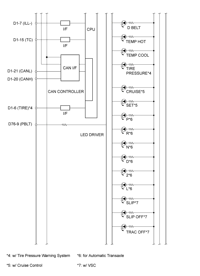
| COMBINATION METER INTERNAL CIRCUIT |


| Terminal No. | Wire Harness Side | |
| D1 | 1 | Ignition switch |
| 2 | Battery | |
| 3 | Fuel sender gauge assembly | |
| 6*1 | Tire pressure warning ECU | |
| 7 | Light control rheostat | |
| 14 | Taillight relay | |
| 15 | Light control rheostat | |
| 16 | Other ECU | |
| 17 | Speedometer sensor | |
| 20 | CAN communication line | |
| 21 | CAN communication line | |
| 24 | Body ground | |
| D76 | 1 | Generator |
| 2 | Brake fluid level warning switch | |
| 4 | ECM | |
| 7*2 | Fog light relay | |
| 8 | Turn signal flasher relay | |
| 9 | Hazard warning signal switch assembly | |
| 10*3 | Washer level warning switch | |
| 11 | Headlight dimmer switch | |
| 12 | Engine oil pressure switch | |
| 13*4 | Headlight dimmer switch | |
| 14 | Headlight dimmer switch | |
| 15 | Turn signal flasher relay | |
| 16*5 | Taillight relay | |
| 17 | Hazard warning signal switch assembly | |
| 18 | Hazard warning signal switch assembly | |
| 19 | Hazard warning signal switch assembly | |
- *1: w/ Tire Pressure Warning System
- *2: w/ Front Fog Light
- *3: w/ Washer Level Warning
- *4: for U.S.A.
- *5: for Canada