Lighting System (For Hatchback) Acc Signal Circuit
DESCRIPTION
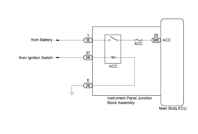
WIRING DIAGRAM
INSPECTION PROCEDURE
READ VALUE USING TECHSTREAM
CHECK HARNESS AND CONNECTOR (INSTRUMENT PANEL JUNCTION BLOCK ASSEMBLY - BATTERY AND BODY GROUND)
CHECK HARNESS AND CONNECTOR (INSTRUMENT PANEL JUNCTION BLOCK ASSEMBLY - IGNITION SWITCH)
REPLACE MAIN BODY ECU
READ VALUE USING TECHSTREAM
LIGHTING SYSTEM (for Hatchback) - ACC Signal Circuit |
DESCRIPTION
This circuit detects the ignition switch ACC or off condition, and sends it to the main body ECU.
WIRING DIAGRAM
INSPECTION PROCEDURE
- NOTICE:
- Inspect the fuses for circuits related to this system before performing the following inspection procedure.
| 1.READ VALUE USING TECHSTREAM |
Connect the Techstream to the DLC3.
Turn the ignition switch to ON.
Turn the Techstream on.
Enter the following menus: Body Electrical / Main Body / Data List.
According to the display on the Techstream, read the Data List.
Main BodyTester Display
| Measurement Item/Range
| Normal Condition
| Diagnostic Note
|
ACC SW
| Ignition switch ACC signal /
OFF or ON
| OFF: Ignition switch off
ON: Ignition switch ACC or ON
| -
|
- OK:
- Normal conditions listed above are displayed.
| 2.CHECK HARNESS AND CONNECTOR (INSTRUMENT PANEL JUNCTION BLOCK ASSEMBLY - BATTERY AND BODY GROUND) |
Disconnect the 3E and 3B instrument panel junction block assembly connectors.
Measure the voltage according to the value(s) in the table below.
- Standard Voltage:
Tester Connection
| Switch Condition
| Specified Condition
|
3E-1 - Body ground
| Always
| 11 to 14 V
|
Measure the resistance according to the value(s) in the table below.
- Standard Resistance:
Tester Connection
| Condition
| Specified Condition
|
3B-8 - Body ground
| Always
| Below 1 Ω
|
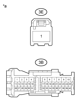
Text in Illustration*a
| Front view of wire harness connector
(to Instrument Panel Junction Block Assembly)
|
| | REPAIR OR REPLACE HARNESS OR CONNECTOR |
|
|
| 3.CHECK HARNESS AND CONNECTOR (INSTRUMENT PANEL JUNCTION BLOCK ASSEMBLY - IGNITION SWITCH) |
Reconnect the instrument panel junction block assembly connectors.
Measure the voltage according to the value(s) in the table below.
- Standard Voltage:
Tester Connection
| Switch Condition
| Specified Condition
|
3B-37 - Body ground
| Ignition switch ACC
| 11 to 14 V
|
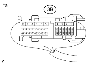
Text in Illustration*a
| Component with harness connected
(Instrument Panel Junction Block Assembly)
|
| | REPAIR OR REPLACE HARNESS OR CONNECTOR |
|
|
Replace the main body ECU (YARIS_NCP93 RM000003TOE00CX.html).
| 5.READ VALUE USING TECHSTREAM |
Connect the Techstream to the DLC3.
Turn the ignition switch to ON.
Turn the Techstream on.
Enter the following menus: Body Electrical / Main Body / Data List.
According to the display on the Techstream, read the Data List.
Main BodyTester Display
| Measurement Item/Range
| Normal Condition
| Diagnostic Note
|
ACC SW
| Ignition switch ACC signal /
OFF or ON
| OFF: Ignition switch off
ON: Ignition switch ACC or ON
| -
|
- OK:
- Normal conditions listed above are displayed.
| | REPLACE INSTRUMENT PANEL JUNCTION BLOCK ASSEMBLY |
|
|
| OK |
|
|
|
| END (MAIN BODY ECU WAS DEFECTIVE) |
|