Lighting System (For Sedan) Ig Signal Circuit
DESCRIPTION
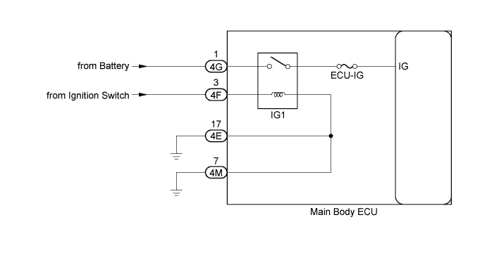
WIRING DIAGRAM
INSPECTION PROCEDURE
READ VALUE USING TECHSTREAM
CHECK HARNESS AND CONNECTOR (MAIN BODY ECU - BATTERY, IGNITION SWITCH AND BODY GROUND)
LIGHTING SYSTEM (for Sedan) - IG Signal Circuit |
DESCRIPTION
This circuit detects the ignition switch ON or off condition, and sends it to the main body ECU.
WIRING DIAGRAM
INSPECTION PROCEDURE
- NOTICE:
- Inspect the fuses for circuits related to this system before performing the following inspection procedure.
| 1.READ VALUE USING TECHSTREAM |
Connect the Techstream to the DLC3.
Turn the ignition switch to ON.
Turn the Techstream on.
Enter the following menus: Body Electrical / Main Body / Data List.
According to the display on the Techstream, read the Data List.
Main BodyTester Display
| Measurement Item/Range
| Normal Condition
| Diagnostic Note
|
IG SW
| Ignition switch signal/
ON or OFF
| ON: Ignition switch ON
OFF: Ignition switch ACC or off
| -
|
- OK:
- Normal conditions listed above are displayed.
| 2.CHECK HARNESS AND CONNECTOR (MAIN BODY ECU - BATTERY, IGNITION SWITCH AND BODY GROUND) |
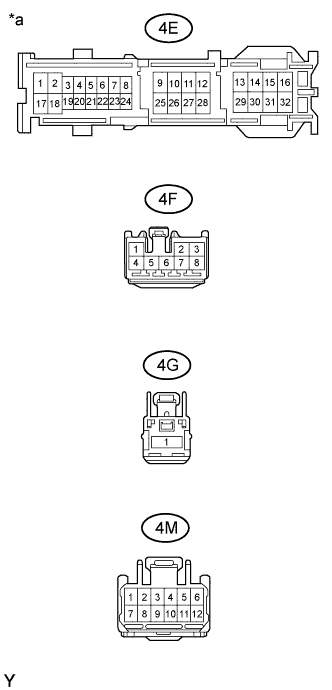
Disconnect the 4E, 4F, 4G and 4M main body ECU connectors.
Measure the voltage according to the value(s) in the table below.
- Standard Voltage:
Tester Connection
| Condition
| Specified Condition
|
4G-1 - Body ground
| Always
| 11 to 14 V
|
4F-3 - Body ground
| Ignition switch ON
| 11 to 14 V
|
Measure the resistance according to the value(s) in the table below.
- Standard Resistance:
Tester Connection
| Condition
| Specified Condition
|
4E-17 - Body ground
| Always
| Below 1 Ω
|
4M-7 - Body ground
| Always
| Below 1 Ω
|
Text in Illustration*a
| Front view of wire harness connector
(to Main Body ECU)
|
| | REPAIR OR REPLACE HARNESS OR CONNECTOR |
|
|